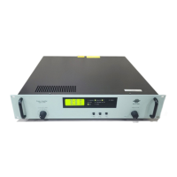
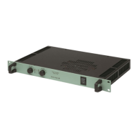
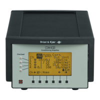
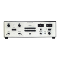
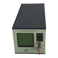
Measuring Ampifier Type 2525
User Manual Vol.1
1–3
BE1406–12
Chapter 1 –Introduction and Specifications
Introduction
1.1.2 Measurement Set-up
The measurement set-up consists of twelve menus which carry out (or lead to sub-
menus which carry out) the following functions:
● Measurement mode selection: acceleration, velocity, displacement or force
● Transducer sensitivity
● Input type: DeltaTron
or Charge (floating or grounded)
● Input, output and fine gain select
● Upper frequency limit
● Lower frequency limit
● Additional filter: Internal, external, none
● Selectable exponential or linear RMS averaging time
● Peak hold time
● Autorange (automatic gain adjustment)
● Alarm: On/off, detector (RMS or peak), level, hold time and level exceed time
● Detector DC output (RMS, peak, voltage)
1.1.3 Interface Control
Under the control of an external computing device via one of its two interfaces, the
amplifier’s extensive measurement and display features can be automated, allowing
full integration in a production line and automated test environment.
All features provided by the menus under manual control (except the specification
of the interfaces themselves) are also available via the interface.
In addition, interface control provides some extra features with respect to resetting
entire set-ups or individual components, error handling, and measurement and op-
eration monitoring and control.
The commands and use of the interface are fully treated in Volume 2 of this manual.
 Loading...
