Measuring Ampifier Type 2525
User Manual Vol.1
6–3
BE1406–12
Chapter 6 –Making a Measurement
Instructions for Measurement
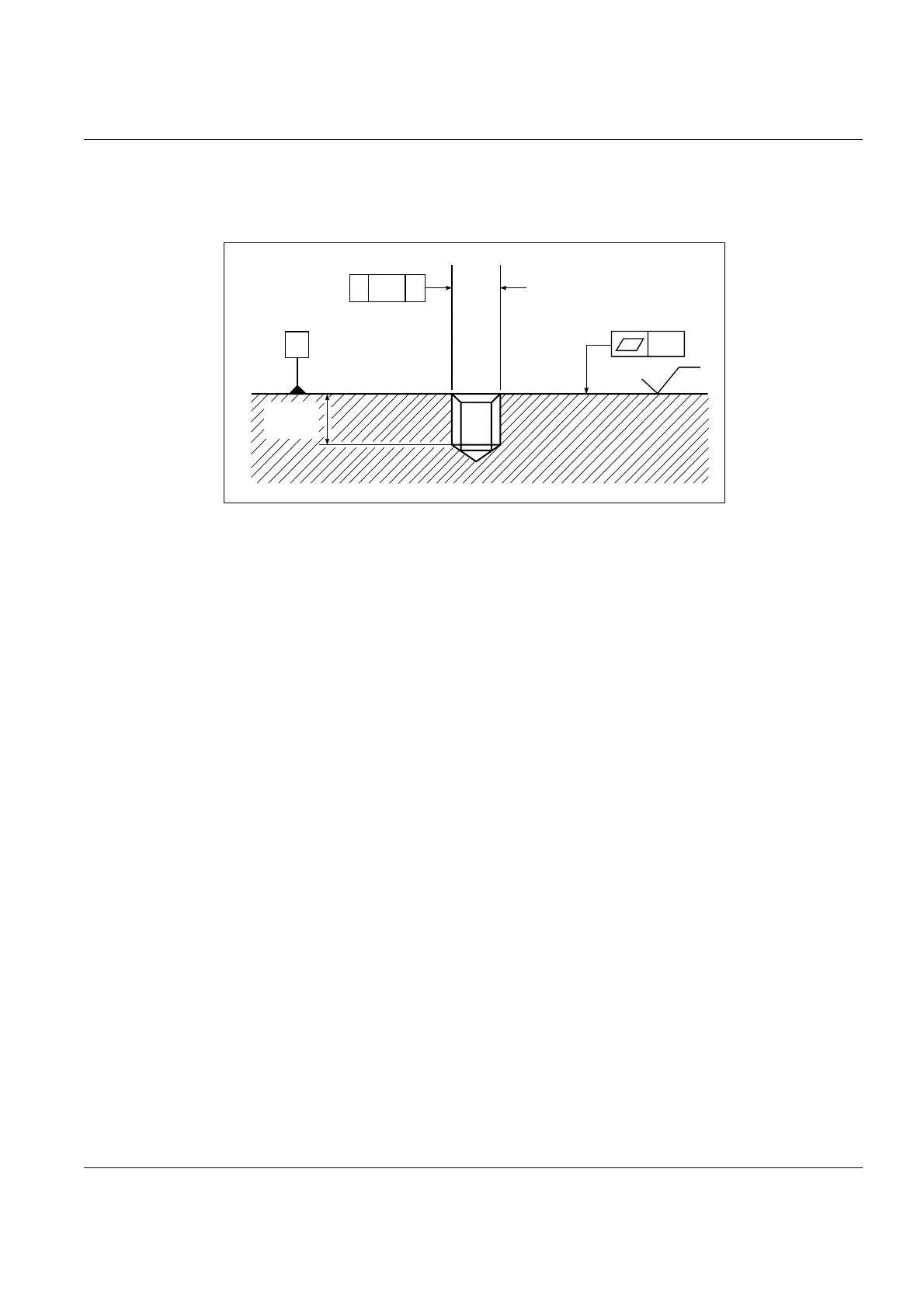
2. If you are using an accelerometer stud, the hole must be tapped according to the
standard shown in Fig.6.1.
3. Choose a location which provides a short and rigid vibration transmission path
to the vibration source. This avoids any compliance and damping elements
present in the structure like gaskets. For example, when measuring vibrations
on rotating machinery, bearing housings are often good places to mount the
accelerometer.
In many cases the accelerometer mounting location is fairly obvious and will be
dictated by your application. In any case, the accelerometer should be mounted
with its main sensitivity axis aligned with the desired measurement direction.
The accelerometer responds to vibrations in directions other than the main sen-
sitivity axis. The red dot on Brüel&Kjær accelerometers can be aligned with the
direction of maximum transverse vibration to minimize their affects.
4. Mount the accelerometer (see section 3.1.5 for grounding).
6.4 Instructions for Measurement
6.4.1 Basic Measurement
1. Place the amplifier on a flat surface. You may want to flip out the feet on the
bottom of the amplifier so that the screen is easier to see.
2. Connect the three-prong mains cable to the contact on the back panel of the
amplifier, and plug into a grounded socket.
Fig.6.1 Recommended tolerances for the mounting surface and
tapped fixing hole. Dimensions and symbols in accordance
with ISO 1101
841363/1e
A
A⊥ ø 0.02
10 - 32 UNF
M3, M4, M5
or M8
0.01
1.6
0.25
Absolute
Min. Depth.
4 mm

 Loading...


