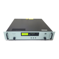
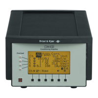
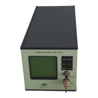
Measuring Ampifier Type 2525
User Manual Vol.1
Brüel & Kjær
5–2
Chapter 5 –The Measurement Set-up Menu
Introduction
5.1 Introduction
The Measurement Set-up menu is chosen from the main set-up menu. The options
available with the measurement set-up menu are discussed in the sections which
follow but may be summarized as follows:
MEASUREMENT MODE For specifying acceleration, velocity, displacement or
force calculations
TRASNDUCER SENSITIVITY For specifying the transducer sensitivity
INPUT TYPE For specifying a grounded or floating charge input, or a
DeltaTron input
GAIN For specifying the input, fine and output gains
UPPER FREQUENCY LIMIT For specifying an upper frequency limit on the meas-
ured signal
LOWER FREQUENCY LIMIT For specifying a lower frequency limit on the measured
signal
ADDITIONAL FILTER For adding and internal or external filter if desired
RMS AVERAGING TIME For specifying the kind of averaging (logarithmic or
linear) and the averaging time
PEAK HOLD TIME For specifying a period over which peak values will be
held by the peak detector
AUTORANGE For carrying out an autorange on the gain values (ei-
ther Output alone or Output and Input gains)
ALARM FUNCTION For specifying an alarm On/Off, its level and duration
DECTECTOR DC OUTPUT For specifying the output calculation on measurement
data
Note: Throughout the sections which follow, “*” indicates the factory-set, default
menu option.
5.2 Measurement Mode
This menu is for selecting the calculations required for the measurement based on
the transducer type used for the measurement. If you are using an accelerometer
you must choose the units for the calculation.
 Loading...
