Measuring Ampifier Type 2525
User Manual Vol.1
Brüel & Kjær
2–4
Chapter 2 –Controls and Connections
Rear Panel
AC Output BNC output socket for connection of measuring and recording in-
strumentation. Produces a maximum output signal of 5V (5mA)
peak. Output impedance is 50Ω.
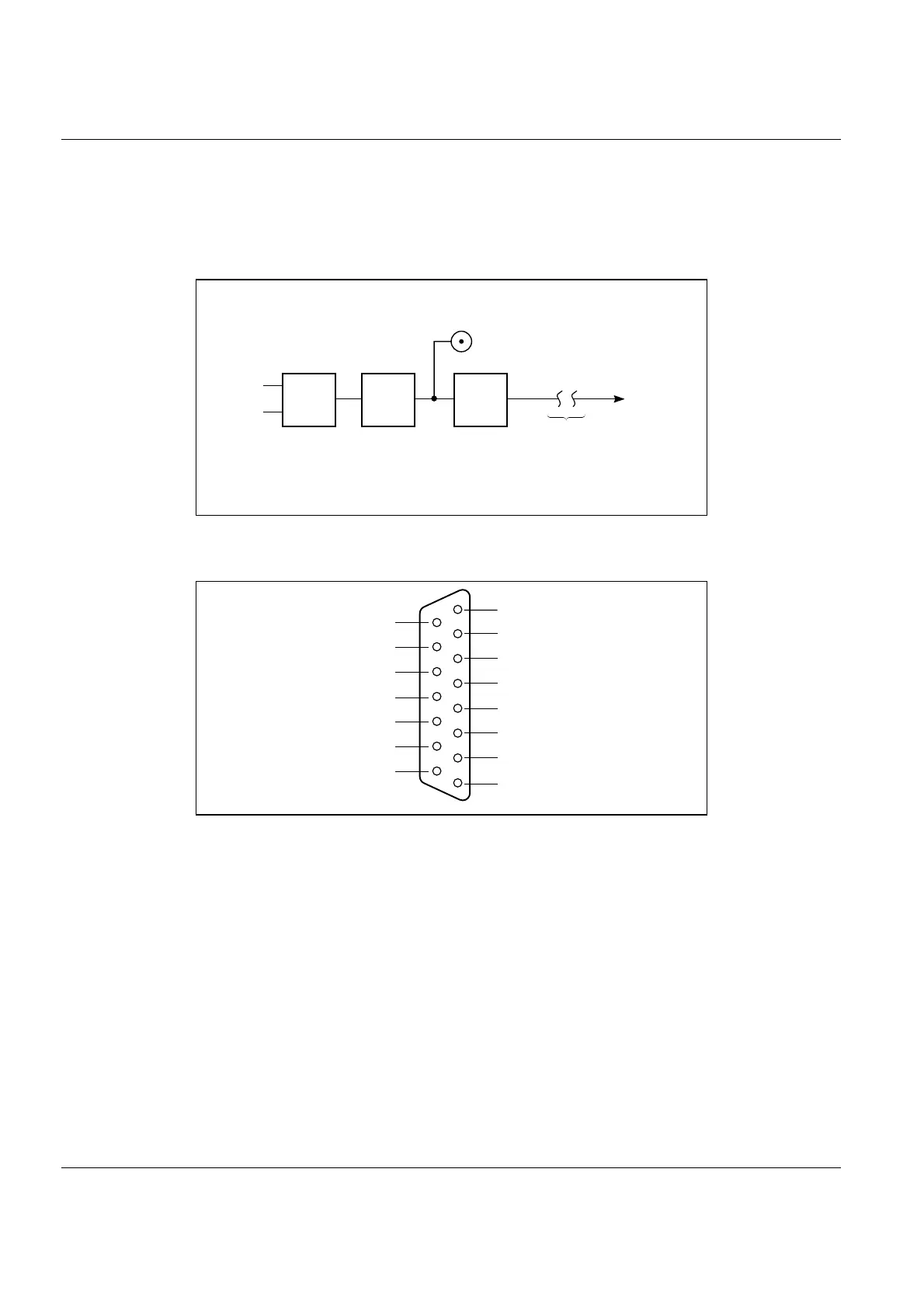
Fig.2.3 Location of Preamp output in 2525 design
Fig.2.4 15-pole auxiliary connector
941571e
Transducer
Input and
Input Gain
DeltaTron
Input
Charge
Input
HP
Filter
LP
Filter
Preamp. Output
To AC
Output
Additional Filter Select
Output Gain
RMS Detector
Peak Detector
Output Amplifier
Acc/Vel Integrators
Type 2525
Simplified Block Diagram
941412e
Ground
Alarm relay, normally open
Detector DC output
Output from external filter,
ground
n.c.
Input to external filter,
signal
Input to external filter,
ground,
Ground
Alarm relay, normally closed
Output from external filter,
signal
Ground
15
14
13
12
11
10
9
8
7
6
5
4
3
2
1
n.c.
n.c.
Ground
Alarm relay, arm
941414e

 Loading...


