Introduction
28 E1400011_1_001
5.3.3 Electronic Control, Magnet and Gradient Unit Connections
The recommended placement of the Gradient Unit in regards to the minispec is with the
Gradient Unit between Magnet and Electronic Control Unit. Cable connections have been
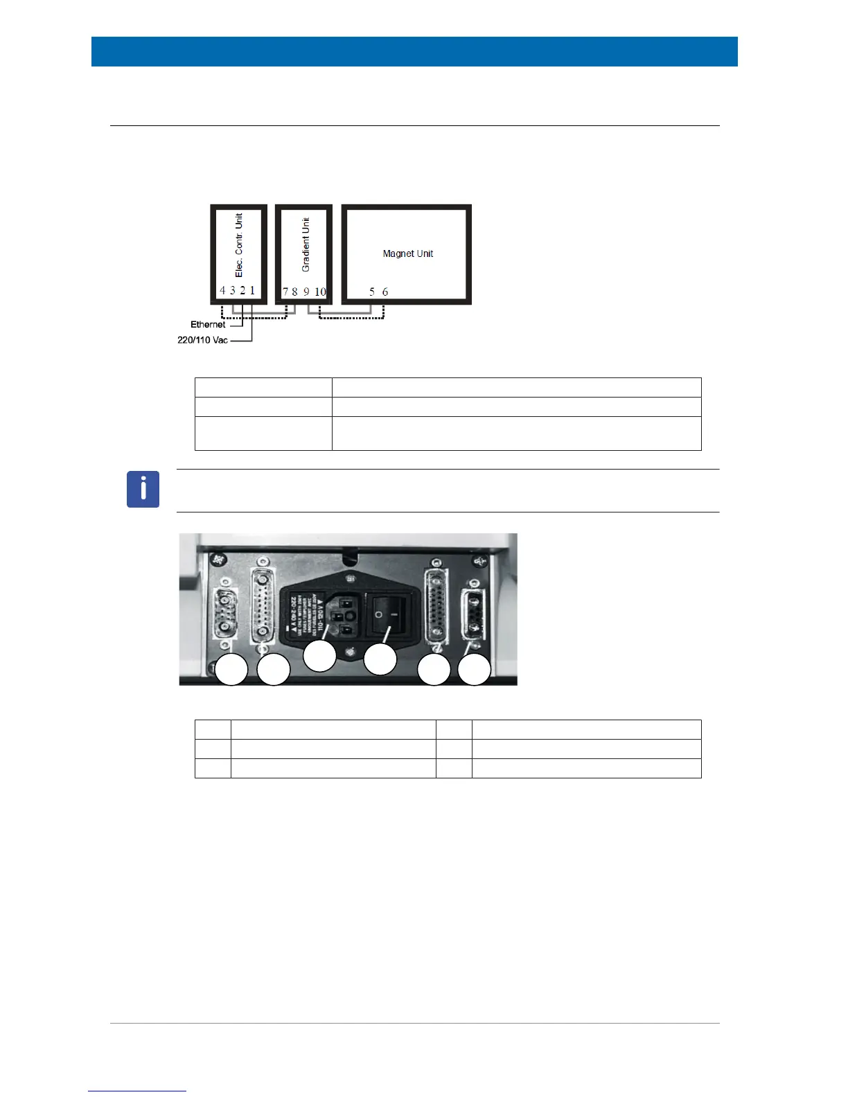
constructed with this layout in mind. The sketch and the photo of the back plane of the
Gradient Unit below indicate the cable connections between the units.
Figure5.6: Sketch of the Back View of the Connections from the Gradient Unit
3 to 8 and 9 to 5 Connections to Electronic Control Unit and Magnet Unit.
4 to 7 Gradient Trigger IN (dotted lines - cable number ‘E 140 1516‘).
10 to 6 Gradient Pulse OUT (dotted lines - cable number ‘E 140
1515‘).
Note: The gradient cables E1401515 and E1401516 must not be mixed up. Otherwise
damage to the minispec units may occur!
Figure5.7: Back View of the Gradient Unit
1. Gradient Trigger IN 4. Power ON/OFF
2. Magnet Unit IN 5. Magnet Unit OUT
3. Mains Power IN 6. Gradient Pulse OUT
 Loading...