Introduction
E1400011_1_001
27
8. Remove and retain the clear plastic dust covers from each component of the minispec and
inspect them for damage.
9. If either unit appears to be damaged, contact your BRUKER representative immediately.
Due to accessories, consumables or optional units packaging may vary. Bruker will make
every effort to deliver the instrument damage free. Therefore, packaging needs to be adapted
to the specific customer order. Due to safety regulations, the system may be packed with
additional shielding elements or may be declared as dangerous goods.
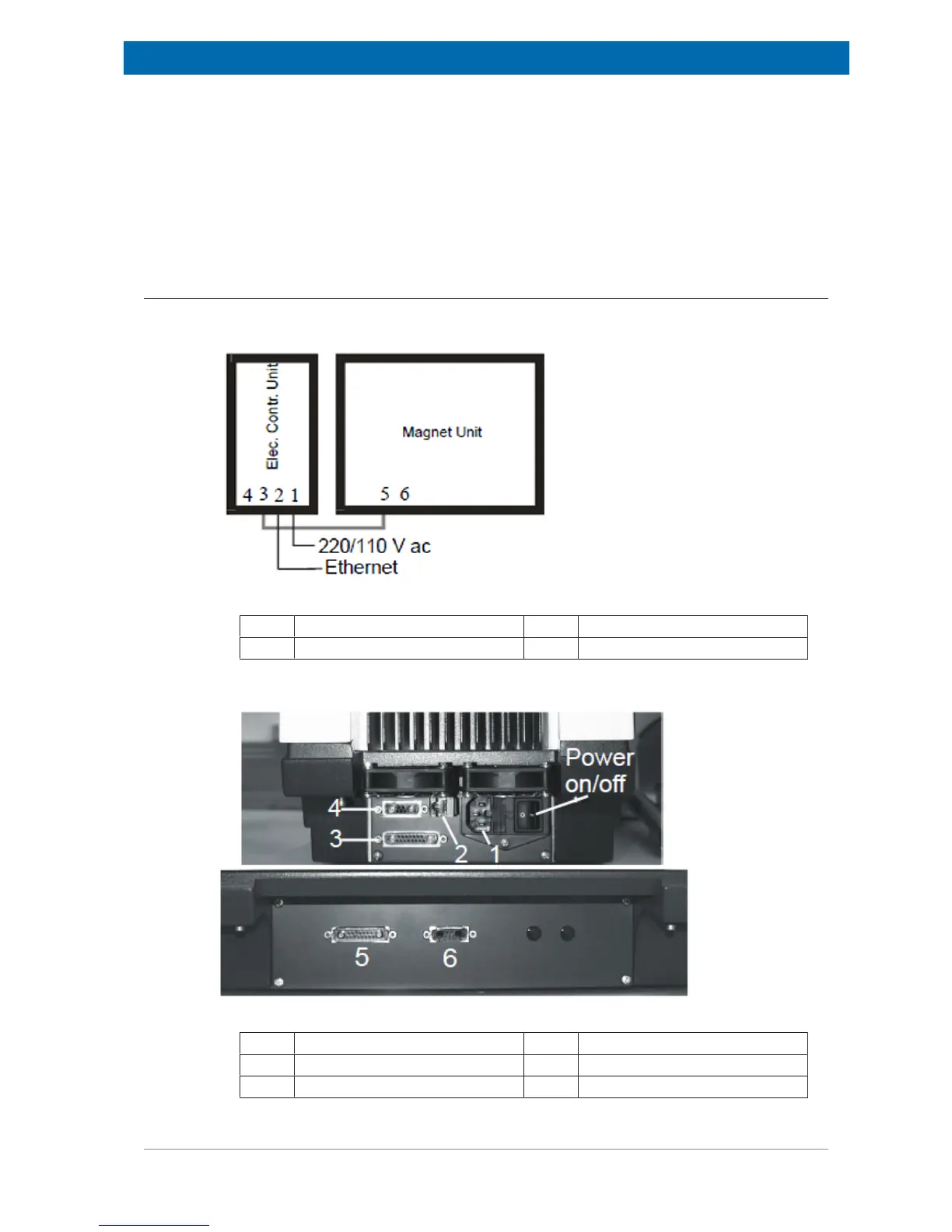
5.3.2 Electronic Control and the Magnet Unit Connections
The connectors are located on the bottom of the back planes. Connect the two units as
shown in the figures below:
Figure5.4: Electronic Control and Magnet Units
1. Main power input. 3 to 5. Connections to the units.
2. Ethernet connection.
Here is an expanded view of the connections:
Figure5.5: Back Planes of the Electronic Control Unit (top) and Magnet Unit (bottom)
1. Mains Power Input 4. Interface to Gradient Unit
2. Ethernet (10 Base T) Connection 5. Interface to Electronic Control Unit
3. Interface to Magnet Unit 6. Interface to Gradient Unit
 Loading...