Technical Data and Installation
SMART WARP - 2.1 -
2
2 2
2 –
––
– TECHNICAL DATA AND INSTALLATION
TECHNICAL DATA AND INSTALLATION TECHNICAL DATA AND INSTALLATION
TECHNICAL DATA AND INSTALLATION
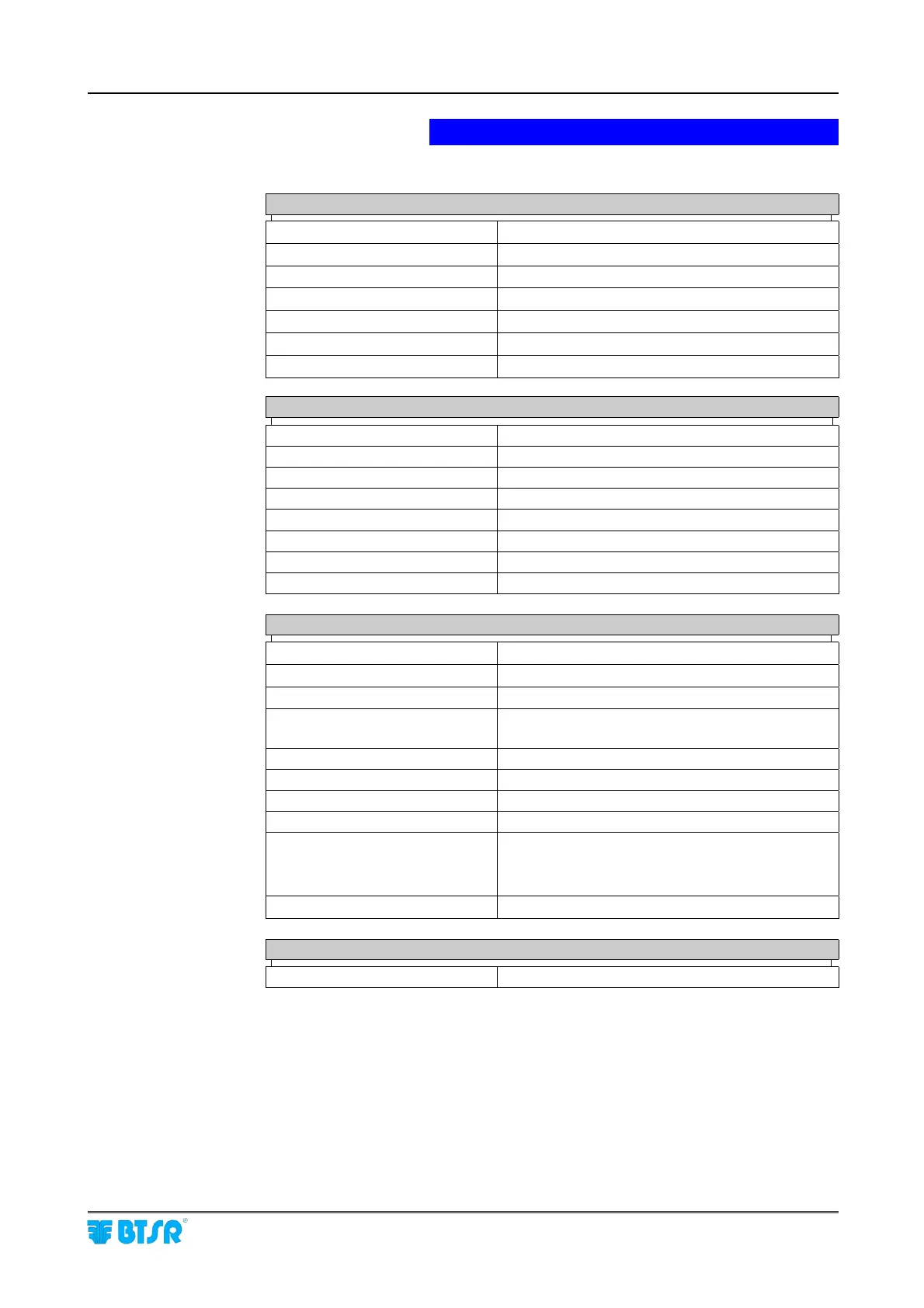
Technical Features
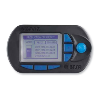
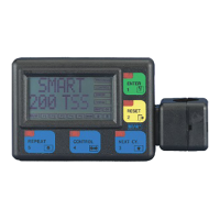
SMART WARP
Terminal
Power supply voltage
15 Vac or 24 Vdc ± 10%
Maximum absorption
150 mA
Dimensions 135 x 95 x 40 mm
Operating Temperature range
0° - 60 °C
LCD graphic display
80 x 40 mm
Integrated Touch-pad 5 membrane buttons with integrated red LED
Protection 2 fuses 5 x 20 – 1A
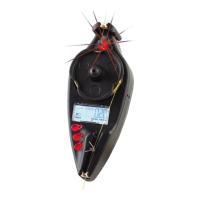
IS3
Sensors
Power supply voltage
24 Vdc ± 20%
Absorption
Typical 12,5 mA (max 20 mA)
Reaction Delay
Programmable from 5 to 1000 msec
Sensitivity
Programmable (10 levels)
Signaling With integrated LEDs (red – green)
Sensor identification Through “Touch Light”
Dimensions 25 x 35 x 10 mm
Temperature range 0° - 60 °C
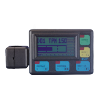
SM-DIN/WARP Modules
Power supply voltage
15 .. 24 Vac or 24 Vdc ± 10%
Absorption
Typical 0.2 A - Max 6 A
2 STOP Outputs (Stop1 - Stop2) NO/NC relay contacts: 0-24 Vac
3 Inputs (Slow Ext - Fast Ext -
Reset Ext)
NO/NC relay contacts: (0-24 Vdc)
Integrated Touch-pad 3 push buttons
Signaling 3 digit display + 8 signaling LEDs
Dimensions 138 x 125 x 35 mm
Operating Temperature range 10° - 70 °C
Mounting type
Inside the cabinet: on DIN rail, or fastening
screws.
On panel: with cover plates
Protection Self-restoring fuse, 5A
Power Supply
Power supply voltage (*) 15..24 Vac ± 10% (by transformer)
(*) The supply voltage to SMART WARP terminal is provided by the connection
cable between terminal and SM-DIN interface module.