2 Burner installation
26 Installation and maintenance instructions Logano GE315 • Issue 02/2006
We reserve the right to make any changes due to technical modifications.
2.7.2 Thermal insulation
z The thermal insulation supplied corresponds to the
respective boiler size (
Table 1). Arrange the thermal
insulation according to the Fig. 32 illustration shown
on the boiler block.
z At the lower boiler area push the insulating material
under the boiler block. The boiler section feet are set
into the cut-outs of the thermal insulation.
Tab. 1:Thermal insulation dimensions
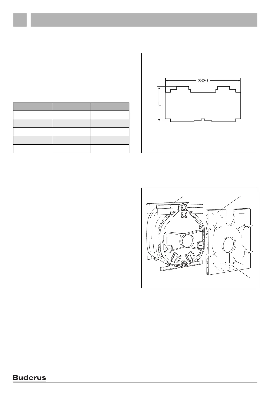
z Slide the thermal insulation for the rear section
(Fig. 33, Item 2) onto the flue gas coupling. Ensure
that the cut-out for the boiler flow and return points
upwards.
z Hook the thermal insulation for the rear section into
the upper cross support bracket using two spring
hooks
(Fig. 33, Item 1).
z Close the gap below the flue gas coupling with spring
hooks
(Fig. 33, Item 3).
Boiler size Boiler segments L
105 5 840
140 6 1000
170 7 1160
200 8 1320
230 9 1480
Fig. 32 Thermal insulation
V: Front (boiler front)
H: Rear (boiler back)
Fig. 33 Installation of thermal insulation at the rear section
V
H
21
3
 Loading...