27
We reserve the right to make any changes due to technical modifications.
Installation and maintenance instructions Logano GE315 • Issue 02/2006
2Burner installation
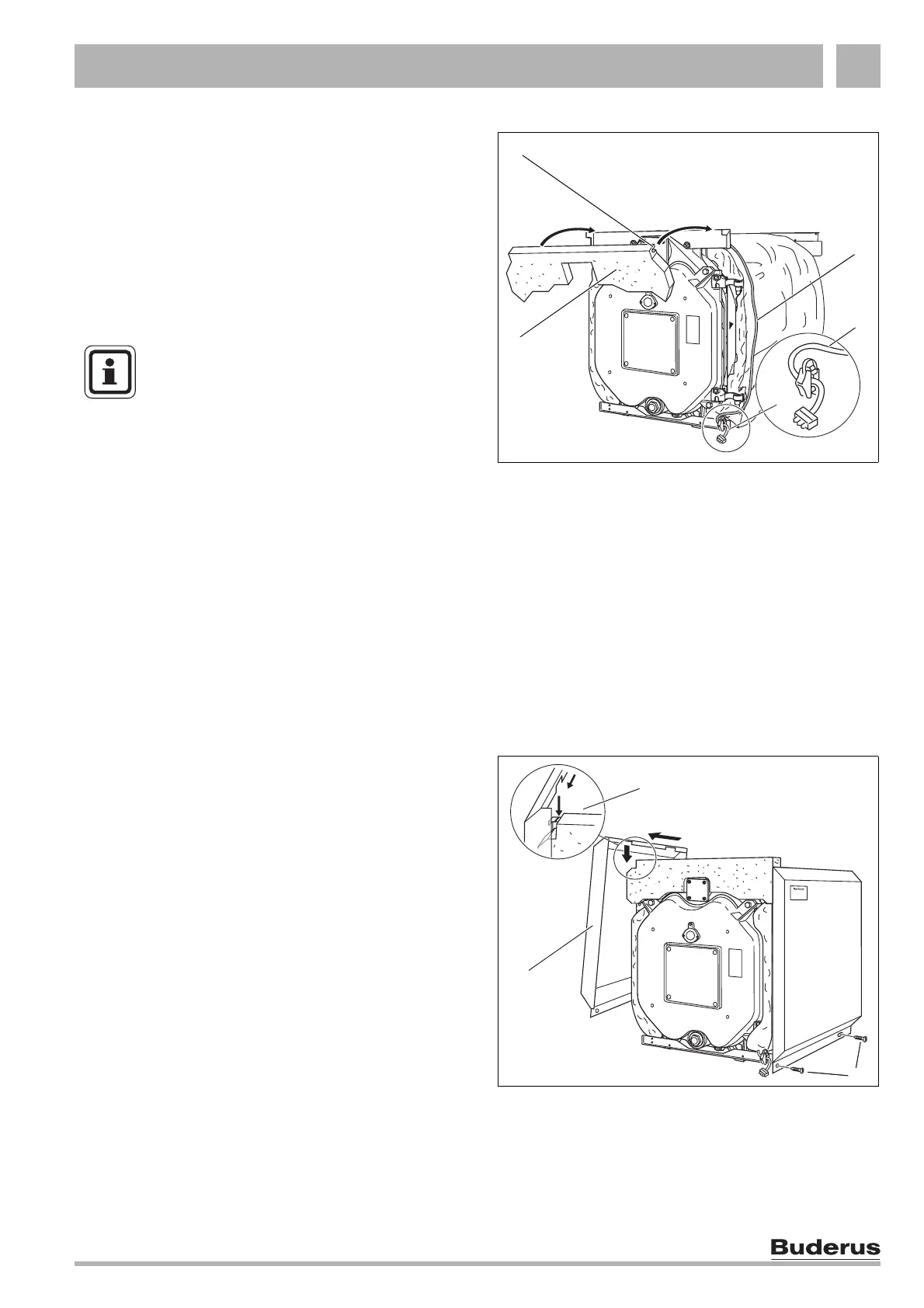
Fig. 34 Installation of the front insulation
Fig. 35 Side casing installation
2
3
4
1
2
3
1
z Slide the front insulation (Fig. 34, Item 1) with its slot
(Fig. 34, Item 2) onto the front edge of the upper
support bracket.
z Lead the burner cable (Fig. 34, Item 3) on top of the
thermal insulation down over the side of the boiler
block.
z With two screws secure the burner cable and strain
relief on the lower cross tie-rod
(Fig. 34, Item 4).
2.7.3 Side and top casing
z Hook the side casing (Fig. 35, Item 1) with cut outs
into the slots of the upper cross support bracket
(Fig. 35, Item 2) and push forward against the end
stop (see arrow in Fig. 35).
z With two self-tapping screws each secure the side
walls at the bottom
(Fig. 35, Item 3).
NOTE!
To prevent the cable being damaged when
opening the burner door, always route the
burner cable – depending on the handing
of the burner door – on the hinge side of
the door.
 Loading...