3-66 2003 Buell P3: Engine
HOME
Bushing Inspection and Removal
1. See Figure 3-103. Bushings are press fit in crankcase
and gearcase cover. Inspect each bushing against its
corresponding cam gear shaft or pinion gear shaft. See
Table 3-30.
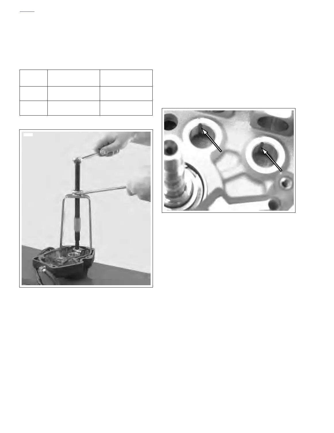
2. See Figure 3-107. To remove bushings from crankcase
and gearcase cover, use BUSHING AND BEARING
PULLER (Part No. HD-95760-69A).
Bushing Installation
NOTE
Installing and reaming crankcase and gearcase cover bush-
ings may alter the center distances between mating gears
and may result in an increase in gear noise. For quiet-running
gears, the gears should be matched to the center distances.
CAM GEAR BUSHINGS IN RIGHT CRANKCASE
HALF
NOTE
See Figure 3-108. Oiling slot in cam gear bushings must be
at the 12 o’clock position
1. See Figure 3-108. Each cam gear bushing, to be
installed in right crankcase half, must be positioned in
crankcase bore with its oiling slot aligned to slot in crank-
case.
2. Using an arbor press, UNIVERSAL DRIVER HANDLE
(Part No. HD-33416), and CAMSHAFT BEARING
INSTALLER (Part No. HD-97273-60, install each bushing
in its crankcase bore so that bushing shoulder contacts
crankcase boss.
3. After you install a new bushing in right crankcase half,
ream the bushing to correct size. See Bushing Reaming.
Table 3-30. Gear Shaft Specifications
GEAR
SHAFT
CORRECT
CLEARANCE
SERVICE WEAR
LIMIT
Cam 0.0007-0.0022 in.
(0.0178-0.0559 mm)
0.003 in.
(0.076 mm)
Pinion 0.0023-0.0043 in.
(0.0584-0.1092 mm)
0.0050 in.
(0.1270 mm)
Figure 3-107. Removing Bushing with Bushing and Bear-
ing Puller (Part No. HD-95760-69A)
7712
Figure 3-108. Cam Gear Bushing Installed in Crankcase
7678