29
Installation
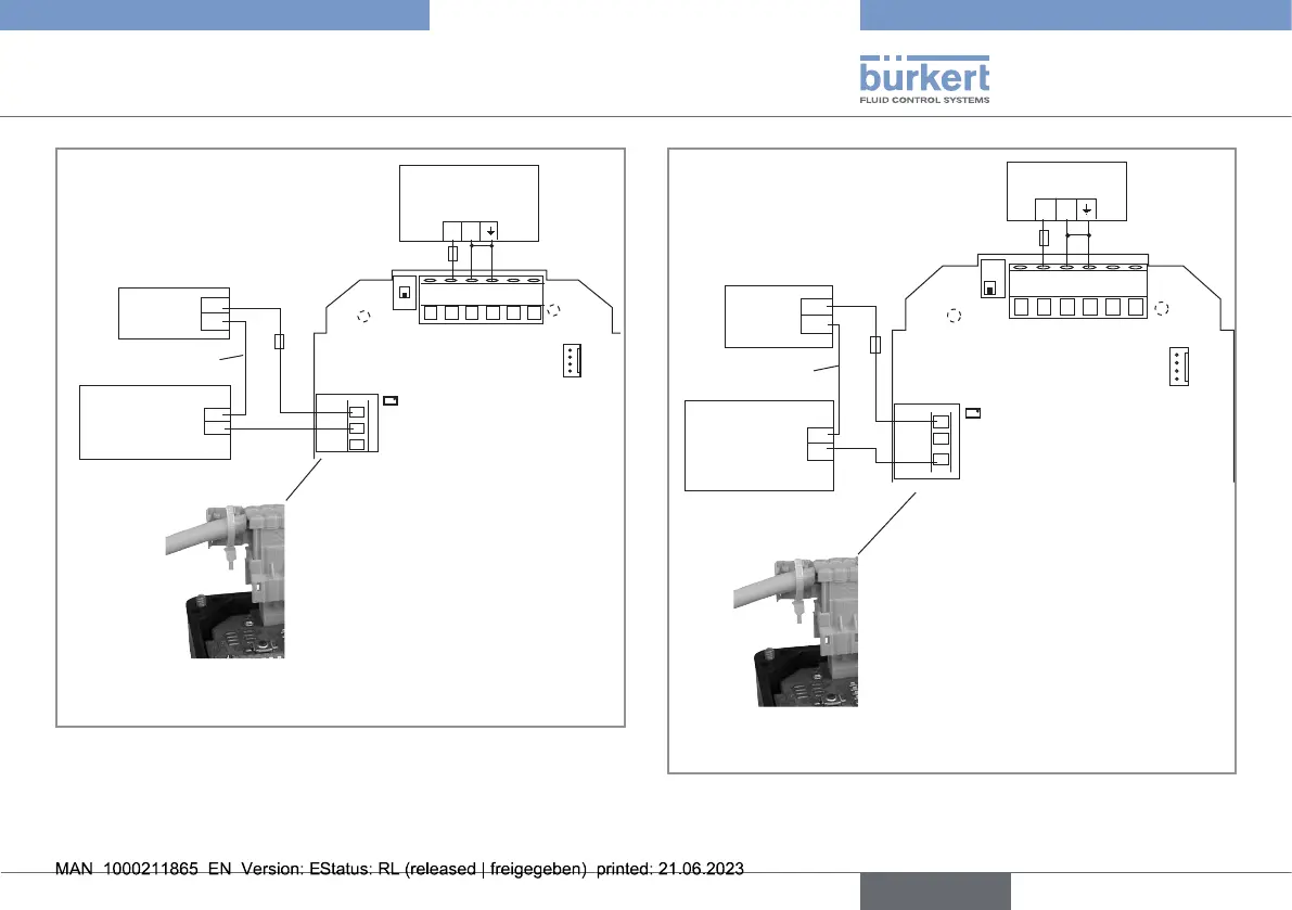
250 V AC
300 mA
8041
NO
C
NC
3 A
+
-
18...36 V DC
L
N
4...20
V+
V-
1
3 4 5 62
PE
Pls+
Pls-
250 V AC, 3 A max.
*
Solenoid valve
(or alarm)
Power supply
Protection circuit
Relay protection cap
* If direct earthing is not possible, connect a 100nF/50V condensator
between the negative terminal of the voltage supply and the earth.
Fig.23: Connectionoftherelayoutputforanormallyopenoperating
+ -
18...36 V DC
250 V AC
L
N
300 mA
3 A
8041
C
NO
NC
4...20 V+ V- PE Pls+Pls-
*
1 2
3
4
5
6
250 V AC, 3 A max.
Power supply
Protection circuit
Relay protection cap
Solenoid valve
(or alarm)
* If direct earthing is not possible, connect a 100nF/50V condensator
between the negative terminal of the voltage supply and the earth.
Fig.24: Connectionoftherelayoutputforanormallyclosedoperating
english
Type 8041