26
Installation
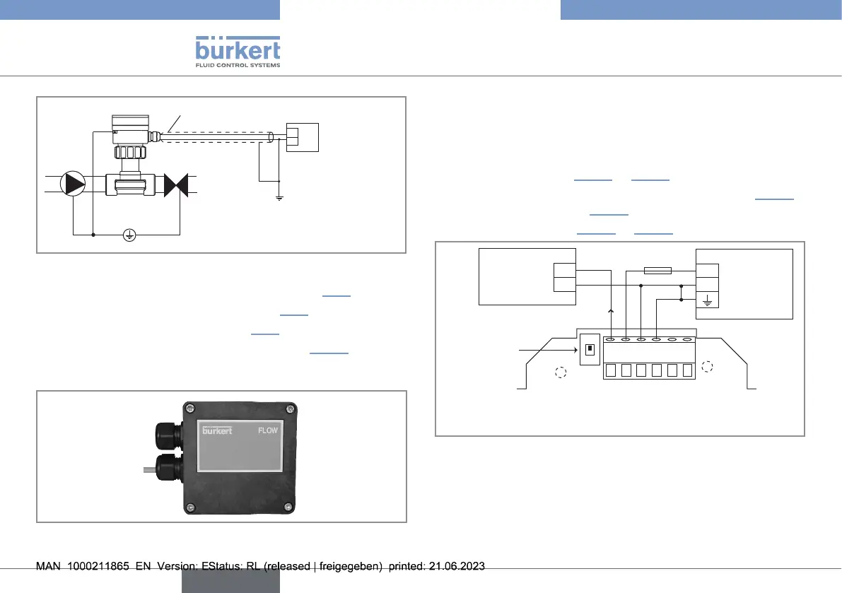
+
-
18...36 V DC
1
2
2
Power cable shield
Power supply
Fig.15: Earthing the device
→ Wire the 4...20mA current output (see chapter8.3.1).
→ Wire the frequency output (see chapter8.3.2).
→ Wire the relay output (see chapter8.3.3).
→ Put the cover of the housing as described in Fig.16.
→ Screw the 4 screws in an alternating pattern.
Fig.16: Positionofthecoverofthedevice
8.3.1. Wiring the 4...20mA output
The current output of the 8041 can be connected to a PLC or a
valve, either in sourcing mode or in sinking mode.
→ Set the selector of the electronic board to the sourcing or the
sinking position (see Fig.17 or Fig.18).
→ Connect the 4...20mA output in sourcing mode (see Fig.17)
or in sinking mode (see Fig.18).
→ Earth the device (see Fig.17 or Fig.18).
1 2 3 4 5 6
V+ V- PE Pls+Pls-
+
-
+
-
*
18...36 V DC
300 mA
I
4...20
Power supply
4...20mA
input at
external
instrument
Selector to
source
* If direct earthing is not possible, connect a 100nF/50V condensator
between the negative terminal of the voltage supply and the earth.
Fig.17: Connectionofthecurrentoutputinsourcingmode
english
Type 8041