25
Installation
Make sure the installation is equipotential (power supply
- 8041):
Connect together the various earth spots in the instal-
lation to eliminate the potential dierences that may
occur between two earthes.
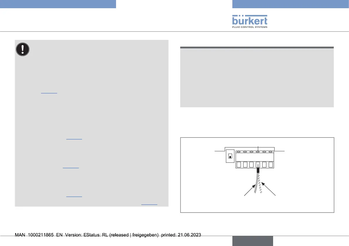
→ In the housing, connect the power supply cable shield
to terminal no.4 of the electronic board connector
(Fig.14
). On a version with stainless steel ow sensor,
a second cable is coming from the sensor.
Connect the negative power supply terminal to the
earth to suppress the eects of common mode cur-
rents. If this connection cannot be made directly, a
100nF/50V capacitor can be connected between
the negative power supply terminal and the earth
(marked1, Fig.15).
If the pipes are made of metal:
connect to the same earth the dierent metallic
instruments (valve, pump...) located near the device
(marks2, Fig.15).
If the pipes are made of plastic:
insert the metal parts (not provided) in the plastic
pipes, upstream and downstream of the device
(marked2, Fig.15).
connect the metal parts to the same earth (Fig.15).
NOTICE
The device is not tight if only one or none of the cable glands
is used
▶ The device is only tight when the cable glands are either
wired or sealed. To seal a cable gland, do the following:
→ Loosen the nut of the unused cable gland.
→ Remove the transparent disk.
→ Insert the supplied blanking plug.
→ Screw the nut of the cable gland.
→ Loosen the nuts of the cable glands.
→ Insert each cable through a nut than through a cable gland.
123456
Power cable shield
Earth cable coming from the
housing
Second cable on a version
with a ow sensor holder in
stainless steel
Fig.14: Earth connection terminal
english
Type 8041