24
Installation
Protect the power supply by means of a 300mA fuse
and a switch.
Do not install the cables near high voltage or high
frequency cables. If this cannot be avoided, observe a
min. distance of 30cm.
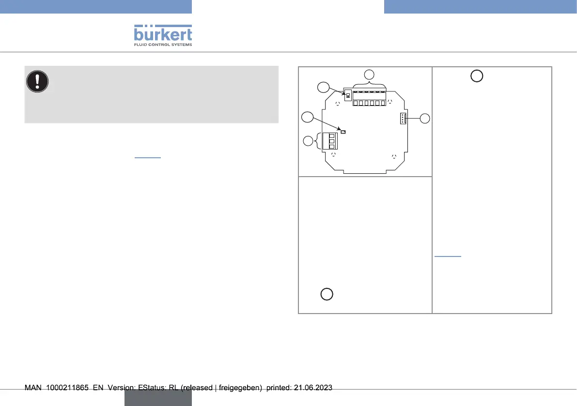
→ Loosen the 4 screws of the cover to access the electronic
board of the device (see Fig.13).
123456
4...20V+V-PEPls+Pls-
C
NO
NC
B
A
2
1
3
Selector
A
: Sink/source
selector of the 4...20mA
output
Terminal block3
Terminal1: 4...20mA output
Terminal2: V+ (positive voltage)
Terminal3: V- (power supply
ground)
Terminal4: PE, shield of
the power supply cable;
Earth cable coming from the
housing and, second cable
on a version with ow sensor
holder in stainless steel (see
Fig.14)
Terminal5: Pls+, positive
frequency output
Terminal6: Pls-, negative
frequency output
Connector1: connection of the at
cable coming from the ow sensor
(to energize the flow sensor)
Terminal block2: wiring the
relay output
C: common point
NO: normally open
NC: normally closed
LED
B
: status LED of the relay
(LED ON = contact closed)
Fig.13:
Terminalassignment
english
Type 8041