36
Adjustment and commissioning
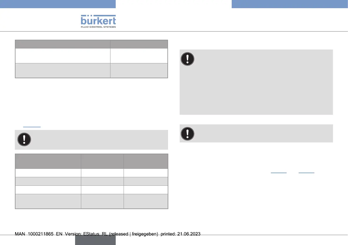
Filter Position of switch3
slow
(Response time 10...90%=14s)
OFF
fast
(Response time 10...90%=5s)
ON
9.6. Selecting the measurement range
The output signal is proportional to the measured ow velocity.
Switches 4 and 5 are used to adjust the measuring range of the
device to your application.
→ Position switches 4 and 5 to select the measuring range (see
Fig.25, and the following table).
After the measuring range has been modied, the per-
centages set for the low and high switching thresholds
are applied to the new full scale selected.
Measuring range Position of
switch4
Position of
switch5
0...2m/s ON OFF
0...5m/s OFF ON
0...10m/s OFF OFF
0 to calibrated full scale
(between 2...10m/s)
ON ON
9.7. Calibrating the ow zero point
→ Calibrate the device on commissioning and after each
maintenance task.
Before calibrating the zero point on commissioning:
immerse the measuring element in the uid for 24h
before calibration.
• Before calibrating the zero point after each maintenance
task:
immerse the measuring element in the uid for 1h
before calibration.
→ Before calibration, ensure that the pipe does not
contain any air bubbles and that the uid is not
→ Fill the pipe with uid.
→ Stop the ow.
→ Calibrate the "zero ow" point (see Fig.27 and Fig.28).
english
Type 8041