9
Description
5.2.2. Operating principle
The magnetic system in the ow sensor generates a magnetic
eld in the uid, perpendicular to the ow direction, see Fig.1.
The electrodes on the ow sensor ensure electrical contact with
the uid. When the uid ows over them, a voltage is measured
between the two electrodes. This voltage is proportional to the
uid velocity.
Fig.1: Operatingprincipleoftheowsensor
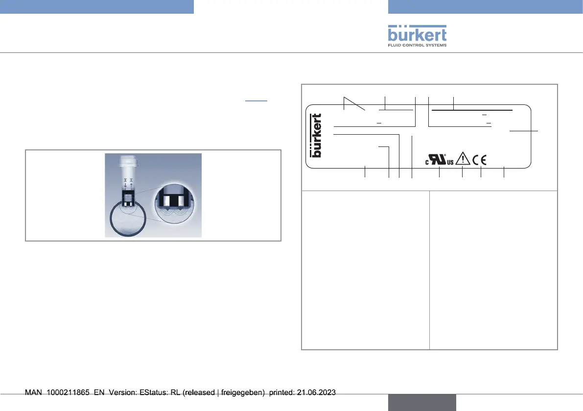
5.3. Description of the rating plate
FLOW: 8041 SST LONG SUPPLY: 18-36V... 220mA
PULSE: 5-36V... 100mA REL: 30V~ or 60V...
I-OUT: 4-20mA IP65 FLUID: PN16; –15/150°C
S/N 1234
00561607 W46MA
Made in France
8
9
1. Measured value and type
of the device
2. Specication of the ow
sensor
3. Specication of the pulse
output
4. Specication of the relay
output
5. Power supply / Max.
consumption
6. Fluid nominal pressure and
uid temperature range
7. Manufacturing code
8. Conformity marking
9. Warning: Before using the
device, take into account
the technical specica-
tions described in the
Operating Instructions
10. Certication
11. Protection class of the
device
12. Specication of the current
output
13. Serial number
14. Article number
Fig.2: Rating plate of the device (example)
english
Type 8041