34
Fluid installation
7.2 Installation of the dosing controller type 8025
Batch in compact version
The dosing controller 8025 Batch is inserted into an S020 fitting mounted on the pipes:
1. Install the S020 fitting on the pipes,
2. Install the 8025 Batch in compact version into the S020 fitting,
3. Finalise the installation of the 8025 Batch in compact version.
7.2.1 Install the S020 fitting on the pipes
→ Select an S020 fitting suitable for the speed of the fluid in the pipes
To select a fitting, refer to the calculation tables on the technical data sheet for the relevant fitting.
→ Choose a position for the fitting according to the design of the pipes, in such a way that:
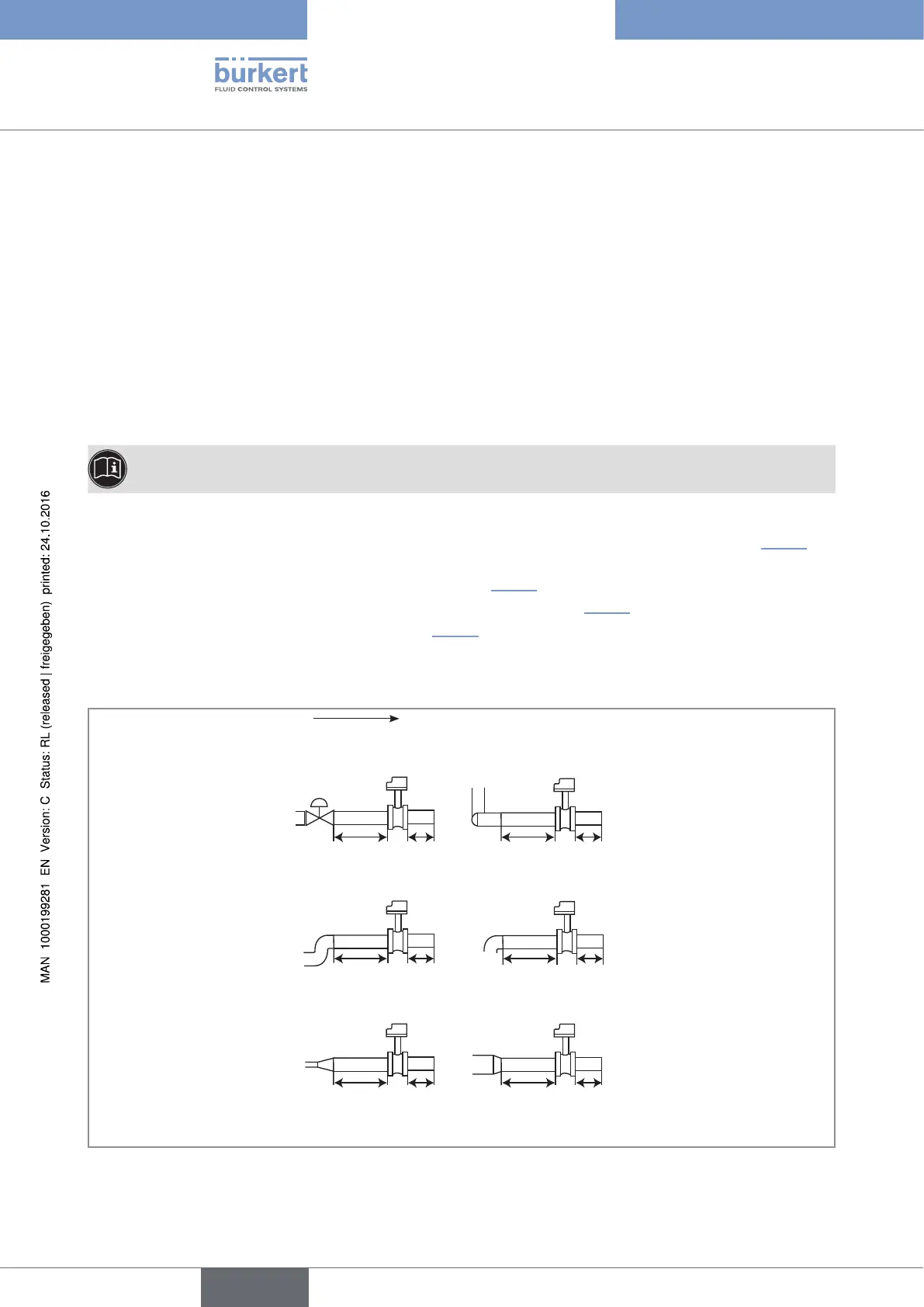
- the upstream and downstream distances are respected according to the design of the pipes, see Fig. 10 and
norm EN ISO 5167-1,
- the pipes are always filled to the level of the sensor (see Fig. 11),
- when mounted vertically, the flow direction of the fluid is upwards (see Fig. 11),
- air bubbles do not form around the sensor (see Fig. 11).
→ If necessary, use a flow conditioner to improve measurement precision,
→ Install the fitting on the pipes according to the instructions in the relevant Operating Instructions.
flow direction
50 x DN 5 x DN
40 x DN 5 x DN
25 x DN 5 x DN 20 x DN
18 x DN 5 x DN 15 x DN 5 x DN
With control valve Pipe with 2 elbows at 90° in 3
dimensions
Pipe with 2 elbows at 90° Pipe with 1 elbow at 90° or 1
T-piece
With pipe expansion With pipe reduction
Fig. 10 : Upstream and downstream distances depending on the design of the pipes.
English
Type 8025 - 8035 - SE35 BATCH