59
Electrical installation and Wiring
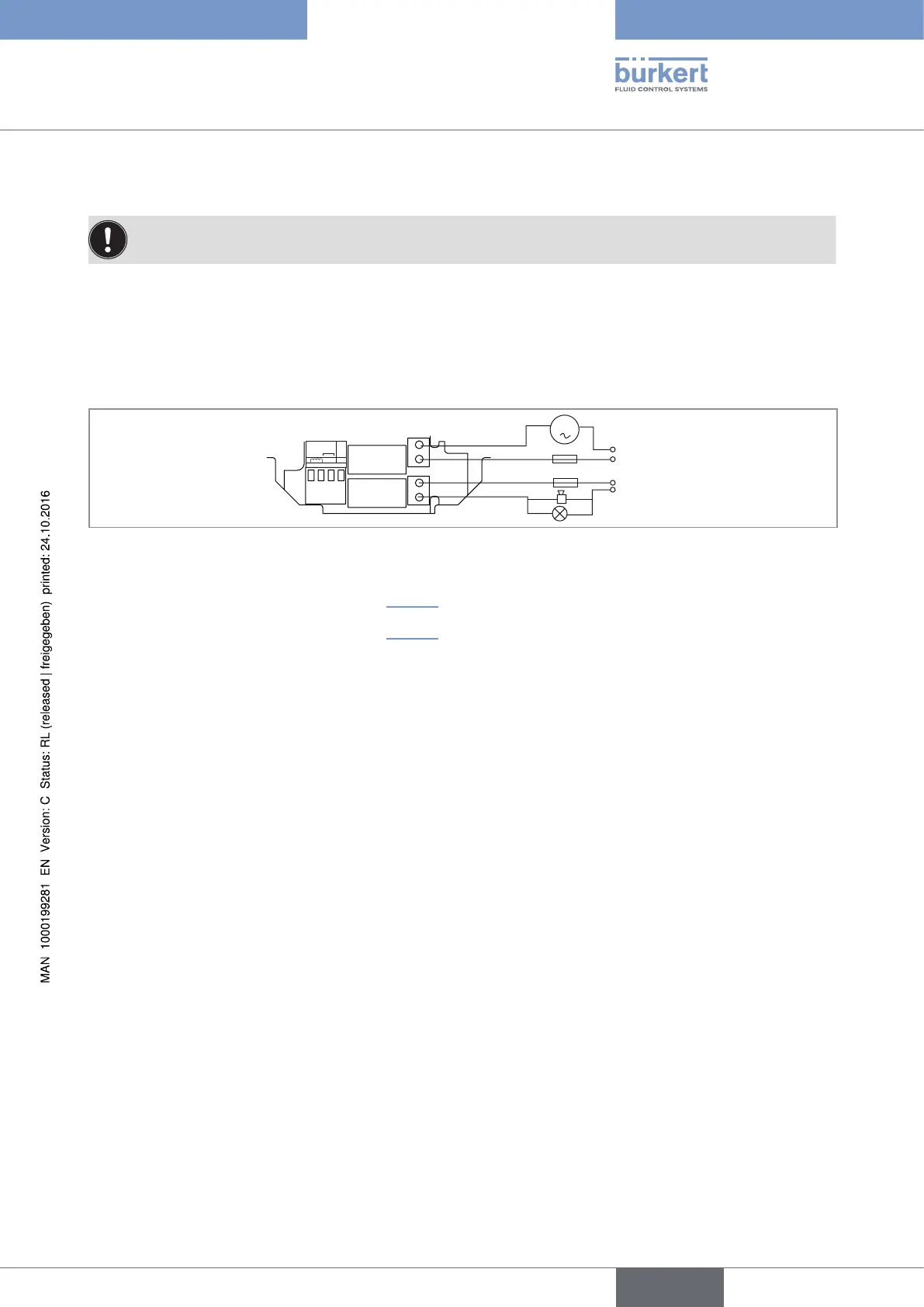
8.14 Wiring the relay outputs DO2 and DO3 of a device
To do a dosing, connect a valve to the relay output DO2.
The device can control:
• either a dosing with a single valve connected to the relay output DO2.
• or a dosing with 2 valves connected to the relay outputs DO2 and DO3. In this case, connect the main valve
(for the highest flow rates) to output DO2 and the auxiliary valve (for low flow rates) to output DO3.
If a single valve is used, connect a load to relay output DO3 suited for the configuration of the output.
FLOW
SENSOR
SUPPLY
NC
COIL
PULSE
INPUT
NPN/PNP
213PE
+-
DO2
DO3
OFFON
3 A
3 A
Fig. 38 : Wiring of the DO2 and DO3 relay outputs
→ To configure relay output DO2, see chap. 10.7.24.
→ To configure relay output DO3, see chap. 10.7.18.
English
Type 8025 - 8035 - SE35 BATCH