40
Fluid installation
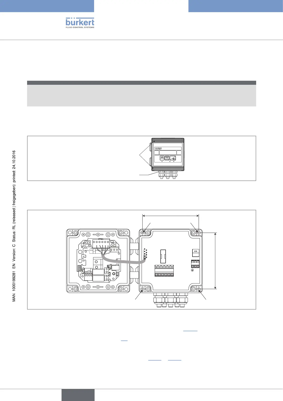
7.6 Installation of the dosing controller 8025 Batch in
wall-mounted version
note
Risk of material damage if the cable glands are not tightly screwed on the housing
▶ Before installing the wall-mounted housing on its support, tighten the nuts of the entry item of the cables
glands at a torque of 1.5 Nm.
The device in a wall-mounted version has 4 holes in the bottom of the housing.
→ Remove the blanking strips covering the screws.
Blanking strips
ENTER
0....9
FLOW
Ffastening nuts
Fig. 18 : Location of the fastening nuts and the blanking strips
→ Loosen the 4 screws and open the cover to get access to the holes [1].
1 1
230V
LN
230V
T 250 mA
56789 10
LN
230V
CURRENT
SOURCE SINK
BINARY
PE PEPE
PE
DI1
DI2
DI3
DI4
DO4
ISOG
FLOW
SENSOR
L+ L- PE P- P+
NC
Iout
PULSE
DO1
Supply
12..36Vdc
Univ
Batch
(AO1)
SUPPLY
NC
COIL
PULSE
INPUT
NPN/PNP
213PE
+-
SENSOR
SUPPLY
LOAD
+5V
L+
(L+)-12V
COIL/PNP
39K
470
2.2K
SENSOR TYPE
COIL NPN/PNP
DO2
DO3
OFFON
106 mm
Fig. 19 : Installation of the dosing controller 8025 Batch in wall-mounted version
→ Secure the housing to the support respecting the dimensions indicated in Fig. 19.
→ Wire according to the instructions in chap. 8.8.
→ Close the housing and tighten the 4 screws of the cover.
→ Set the K-factor or determine it with Teach-In (see chap. 10.7.3 or 10.7.4).
English
Type 8025 - 8035 - SE35 BATCH