84
Operating and functions
10.6.6 Doing a dosing in dosing mode "EXT. REP."
The dosing mode "EXT. REP." allows for starting, via the digital inputs, the dosing of the quantity determined by a
Teach-In procedure.
Danger
Danger due to electrical voltage.
▶ Disconnect the electrical power for all the conductors and isolate it before carrying out work on the system.
▶ Observe all applicable accident protection and safety regulations for electrical equipment.
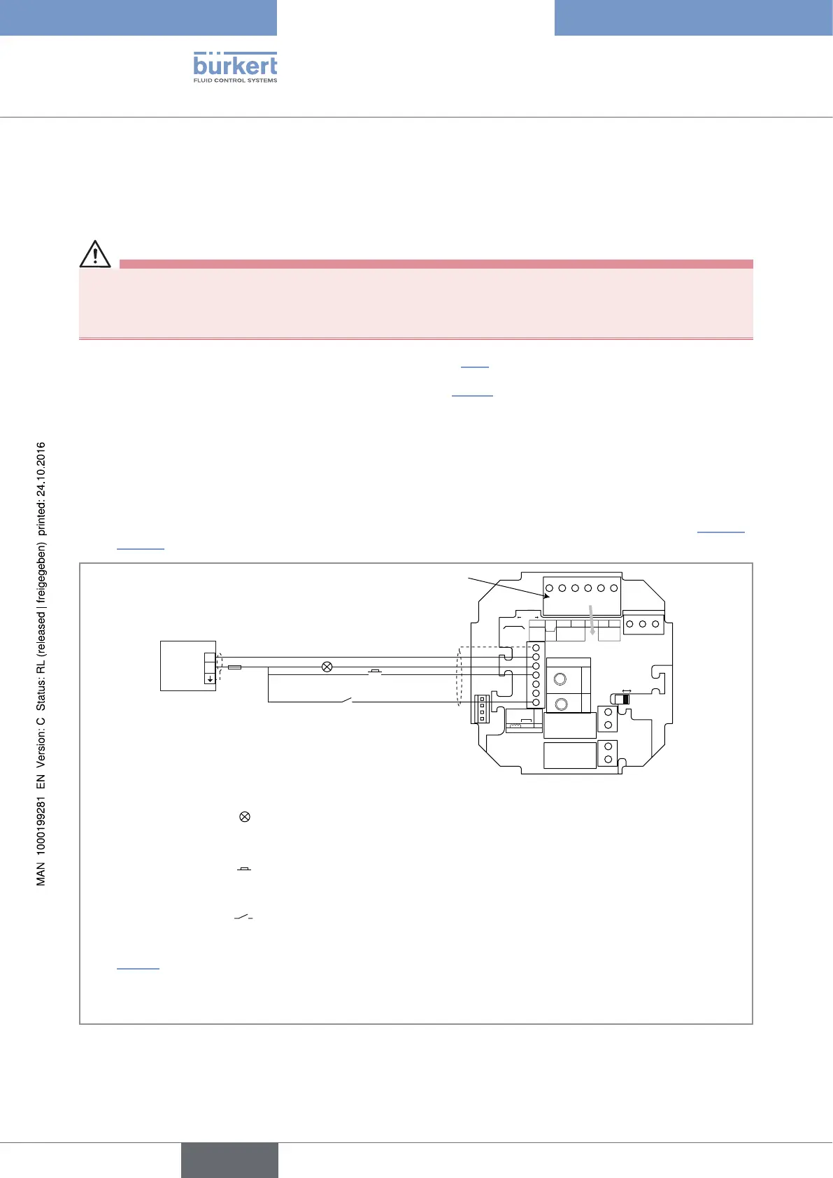
→ Connect the valves to the DO2 and DO3 outputs: see chap. 8.14.
→ Wire the output DO4 and the digital inputs as described in Fig. 52 and depending on the following
requirements:
• the transistor output DO4 allows for transmitting the dosing state.
• when a dosing has been interrupted, the digital input DI1 allows for the navigation within the pause menu,
between the function "CONTINUE" and the function "RESET".
• the digital input DI4 allows for interrupting or continuing a dosing, when the digital input DI1 is active. It also
allows for confirming an alarm, if the generation of alarms has been activated on the device (see chap. 10.7.16
and 10.7.17).
CURRENT
SOURCESINK
BINARY
PE PEPE
PE
DI1
DI2
DI3
DI4
DO4
ISOG
FLOW
SENSOR
L+ L- PE P- P+
NC
Iout
PULSE
DO1
Supply
12..36Vdc
Univ
Batch
(AO1)
SUPPLY
NC
COIL
PULSE
INPUT
NPN/PNP
213PE
+-
SENSOR
SUPPLY
LOAD
+5V
L+
(L+)-12V
COIL/PNP
39K
470
2.2K
SENSOR TYPE
COIL NPN/PNP
DO2
DO3
OFFON
+
-
5-36 V DC
125 mA
LED
1)
signalling the dosing state for example if the output DO4 has been
configured to transmit the state of the device.
System enabling to start and interrupt the dosing.
Switch
Terminal A
PLC
2)
1)
The LED can be replaced by another indicating system depending on the configuration of the transistor output DO4. See
chap. 10.7.18.
2)
On a version energized with a 12...36 V DC voltage, the power supply of the device can be used to energize the digital
inputs DI and the transistor output DO4; If this is the case, connect the terminal "ISOG" to the terminal (L-) of terminal block
A and use a 300 mA-fuse (instead of a 125 mA-fuse) to protect the power supply.
Fig. 52 : Electrical connection of the digital inputs DI and of the transistor output DO4 in the dosing mode "EXT. REP"
English
Type 8025 - 8035 - SE35 BATCH