20 2020/06 - Indice de révision : A -
4. Setting and programming ends of travel
The ends of travel are managed by a printed circuit board. An electrical panel is used to program the ends of
travel.
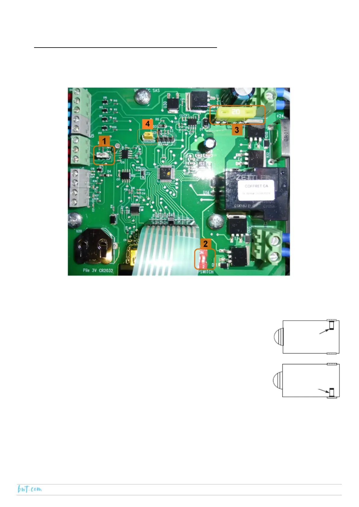
4.1. The printed circuit board
Number 1: Jumper
There are two possible positions for the jumper, the position is selected depending on the motor drive system.
In the case of an AX-IN motor, the jumper connects the right-hand side pine and the centre pin.
Number 2: Dipswitch
Dipswitch number 1 is used to change the direction of rotation of the motor, this will
depend on the side of the pool on which the motor is located (refer to the figure
opposite):
‐ Motor on the right-hand side: dipswitch 1 should be set to OFF
‐ Motor on the left-hand site: dipswitch 1 should be set to ON
Dipswitch number to 2 is used for the anti-tear (“ON” deactivated).
Number 3: Fuse
The board should never be fitted with a fuse with a rating above 20 A. The use of a fuse rated for the automatic
cover motor is highly recommended.
In the case of an AX-IN-120 motor, place the 7.5 A fuse (supplied) on the PCB.
In the case of an AX-IN-300 motor, place the 10 A fuse (supplied) on the PCB.
Number 4: Reset
This is used to reset the PCB.
RH side
LH side