24 2020/06 - Indice de révision : A -
Take up the coping at the points where the sub-coping support plates will be installed.
The surfaces that will receive the sub-coping support plates must be completely flat
and level.
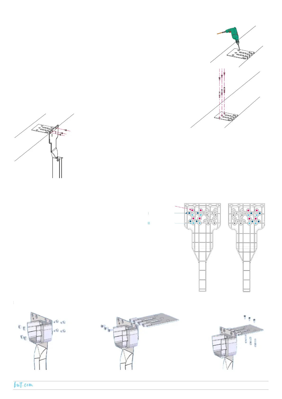
• Position the plates as shown in the diagram (configuration with standard extension).
• Position the pit wall flanges such that the front of the pit wall is level with the centre
of the beam support shoe.
• Using the 13 mm concrete drill bits, counter drill at the location of the
circular holes.
• Fix in position using bushings, M8 x 50 A4, and countersunk hex socket
screws M8 x 20.
Important: Do not replace the coping until installation of the
separating pit wall is complete.
Fasten the pit wall flanges to the support plates using 3 countersunk hex socket
screws M8 x 20.
Position the beam support shoe according to the
type of coping.
Using an M8 drill bit, drill the pit wall flange at the
locations corresponding to the position of the beam
support shoe
The assembly described below concerns the left-hand
side.
 Loading...