Viper SC+™ IP Router for Licensed Spectrum PN 001-5008-000 Rev. C | Page 5
SETUP / COM port
Pin-Out
Contact Numbering
(1)
Programmable
(2)
Always asserted
(3)
Future use
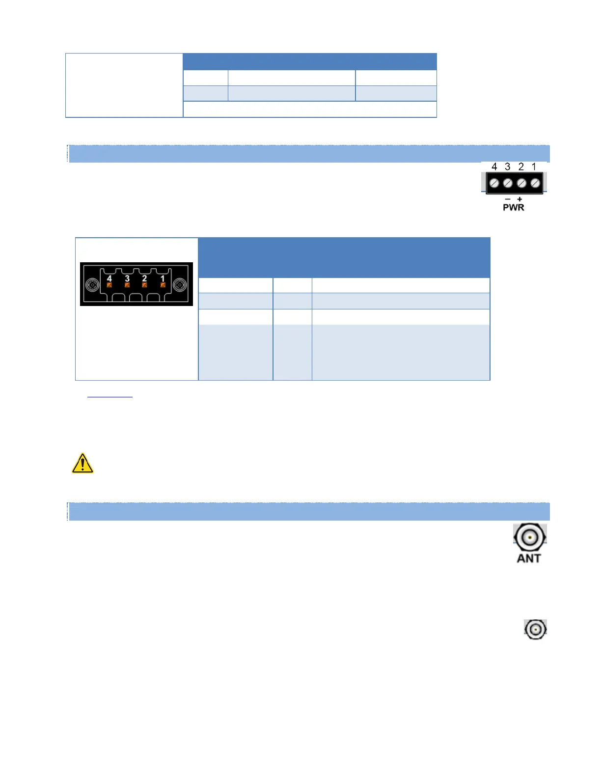
1.3.3.3. Power Connector
Viper is supplied with a right-angle power connector (10-30 V DC). The following table shows the
pin-out of the power connector.
Table 5 – Pin-Out of the Power Connector
Contact
number
(Left to Right)
Enable to Power Management — See
Note
Power – Viper is awake.
No Power – Viper is asleep.
See Appendix B for detailed voltage and current requirements.
Note: The white Enable line must be tied to the red positive lead of the connector for the Viper to power up and
function.
WARNING – EXPLOSION HAZARD - Do not disconnect unless power has been removed or the area is
known to be non-hazardous.
1.3.3.4. Antenna Connector
Standard Viper SC+ models have a 50 ohm TNC female antenna connector. This connection functions for
both transmit and receive.
Warning: See Selecting Antenna and Lightning Arrestor combinations for information about types of lightning
arrestors to not use and good design practices to use when selecting a lightning arrestor for use with an antenna.
Dual port models feature a 50 ohm TNC female antenna connector functioning for transmit (only) and a 50
ohm SMA female antenna connector functioning for receive (only). The separate receive antenna connector is
ideal for applications that require additional receive filtering, external PA(s) and other options.
Warning: The transmit antenna port must not be connected directly to the receive antenna port of the Dual Port
Viper SC+. Excessive power into the receive antenna port will damage the radio. Input power to the receiver should
not exceed 17 dBm (50 mW).

 Loading...