Viper SC+™ IP Router for Licensed Spectrum PN 001-5008-000 Rev. C | Page 158
To set up the Viper SC+ to enable or disable PSM using the command-line interface (CLI), use either of the following
two commands:
set low.power.mode=0 ;(disables PSM.)
set low.power.mode=1 ;(enables psm, follows the state of the “ignition sense” signal)
save ;(when selecting either mode, enter save to save your setting.)
Selecting Power Management to Enable (follow ignition sense) as shown above, allows the white Ignition Sense line to
control the PSM of the Viper SC+.
Normally the White ignition sense line or “Enable” line is tied to the B+ supply along with the Red B+ wire. When used
for PSM, the white wire is connected to a line that will toggle from B+ to OFF. When B+ is applied, the Viper SC+ will be
powered up as normal. When B+ is removed, the PSM sleep mode is enabled in less than 500 milliseconds (500 ms, or
0.5 sec).
When B+ is reapplied to the White wire, the Viper SC+ will wake up and be in full operation mode in approximately one
second (1 s) if VPN is not used. If VPN is used, wake-up time will be less than or equal to five seconds (5 s). Wake-up
time may increase if the system is congested since VPN requires the keys to be updated from the VPN server.
The following table shows the maximum current drain used by the White wire. Input voltage is from +10 V DC to
+30 V DC. This will allow the user to size the DC switching line to control this feature.
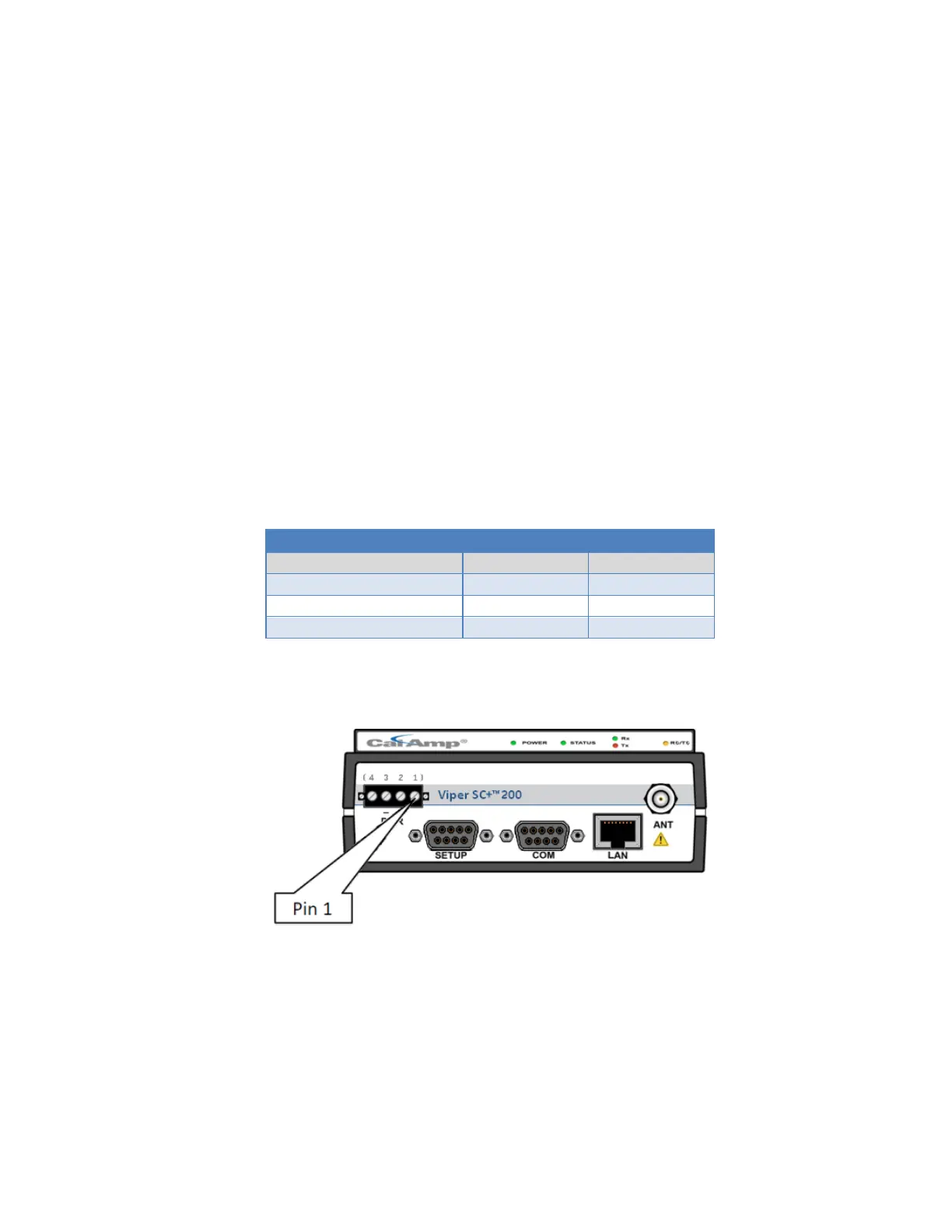
The following figure shows the Viper SC+ power connector and identifies the location of Pin 1 used for ignition sense.
Figure 80 – Viper SC+ Power Connector Pin 1
The amount of current drain will vary for each radio. Initial testing has shown a current drain of approximately 130 mA
at +12 V DC input. This is a power consumption of less than 1.6 W. These are average readings and are not a
guaranteed specification. Please Contact CalAmp Wireless Networks Group Technical Support with any questions.
Technical Support can be reached at:
Email: productsupport@calamp.com
Phone: 1.507.833.6701 Option 2 for Fixed, narrowband, and radio modem products.

 Loading...