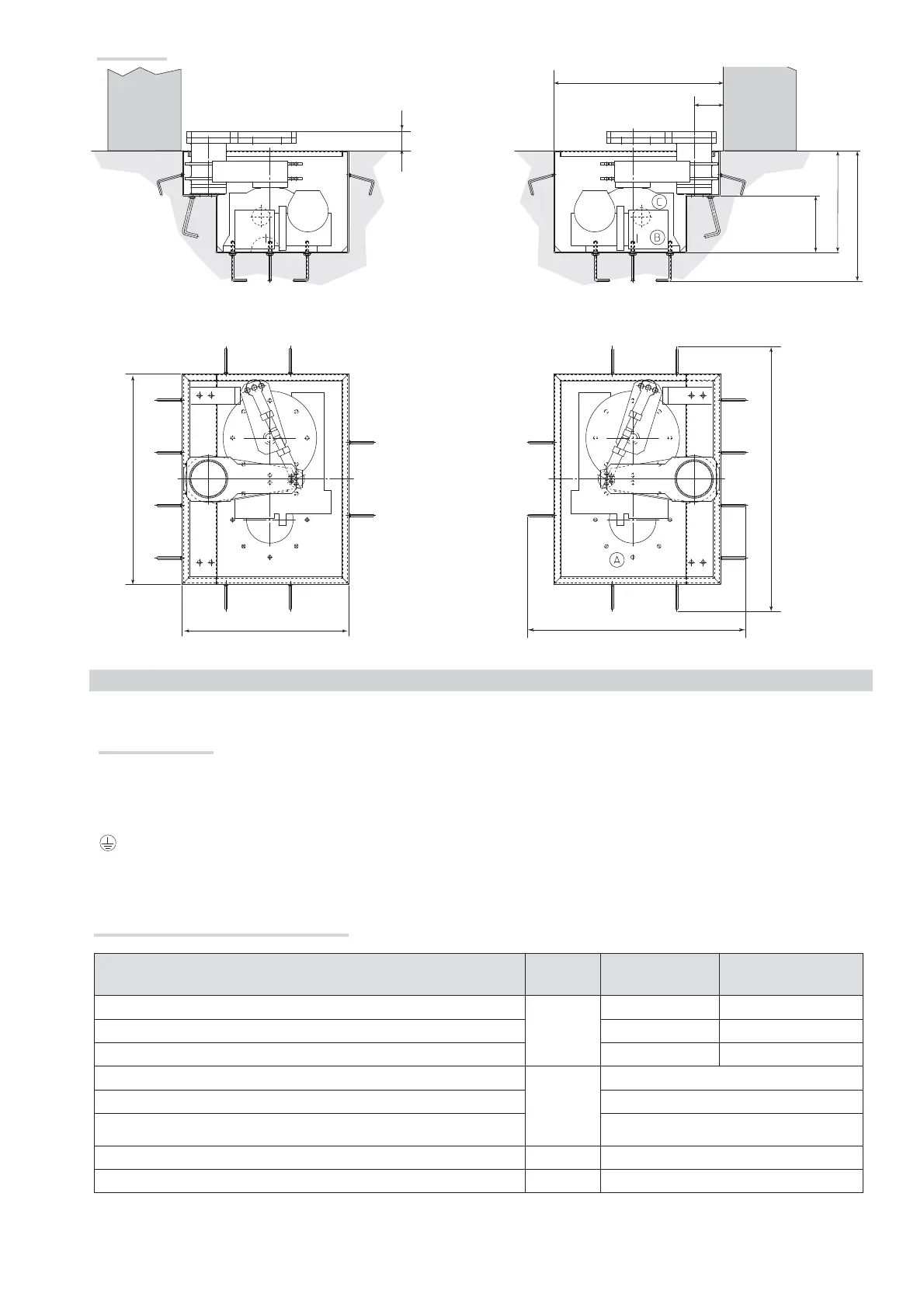
447.5
350
195
580
100
64
720
570
~ 850
~ 1000
Page
5 -
Manual code:
FA00598-EN ver.
1 05/2018
© CAME S.p.A. - The data and information provided in this manual are subject to change at any time without prior notice by CAME S.p.A.
Dimensions
GENERAL INSTALLATION INSTRUCTIONS
⚠
Installation must be carried out by qualified and experienced personnel in compliance with applicable regulations.
Preliminary checks
⚠
Before installing the operator:
• Provide a suitable single-pole disconnection device, with a maximum of 3 mm between the contacts, to disconnect the power supply;
• Prepare suitable piping and ducts for routing the electrical cables, ensuring protection against mechanical damage;
• Prepare a drain pipe to prevent stagnation that may cause oxidation;
•
Make sure that any connections within the container (made to ensure the continuity of the protection circuit) are fitted with additional insulation
compared to the other internal conductor parts;
• Make sure the gate structure is sturdy enough, that the hinges are in proper working order and that there is no friction between the moving and fixed parts;
• Make sure there are opening and closing mechanical stops.
Types of cables and minimum thicknesses
Connection
Cable
type
Cable length
1< 15 m
Cable length
15 < 30 m
Control panel power supply 230 V
H05RN-F
3G x 1,5 mm
2
3G x 2,5 mm
2
Motor power supply 230 V 4G x 1,5 mm
2
4G x 2,5 mm
2
Flashing light 2 x 0,5 mm
2
2 x 1,5 mm
2
Photocell transmitters FROR CEI
20-22
IEC EN
50267-2-1
2 x 0.5 mm
2
Photocell receivers 4 x 0.5 mm
2
Control and safety devices 2 x 0.5 mm
2
Encoder TWISTED max 30 m
Antenna RG58 max 10 m
N.B.: If the cables differ in length from what shown in the table, the cable cross-section is determined according to the actual current draw of the devices
connected and according to the provisions of the IEC EN 60204-1 standard.
For connections that require several, sequential loads, the sizes given on the table must be re-evaluated based on actual power draw and distances. When
connecting products that are not specified in this manual, please refer to the documentation provided with said products.