0.4 01/2012
© CAME cancelli automatici s.p.a. -
The data and information reported in this installation manual are susceptible to change at any time and without obligation on CAME cancelli automatici s.p.a. to notify users.
ENGLISH
Blue
Violet
Orange
White
Red
Brown
Black
Grey
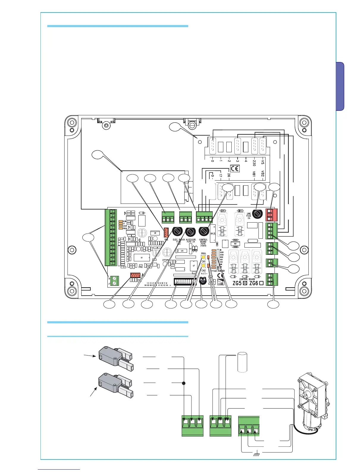
6.1 Main components
6.2 Electrical connections
230V (a.c.) Motor
Gearmotor, mechanical stops
Opening-microswitch
Orange
Orange
Red
White
Blue
Black
Closing-microswitch
1 - Line fuse
2 - Control unit fuse
3 - Accessories fuse
4 - Electroblock fuse
5 - Powersource Terminals
6 - Transformer Terminals
7 - Electroblock Terminals
8 - Endpoint assembly Terminals
9 - Coupled Barrier Terminals
10- Encoder Terminals
11- Connections Terminals
12- Radiofrequency Card input (see table on page 20)
13- RSE serial card input (optional for connection coupled
barriers and/or compass)
14- TCA Trimmer: adjusts automatic closing time
15- Function selector Dip switch
16- Radio code storing buttons
17- Signalling LEDs for radio codes/automatic closing
18- Gate run counter
19- Motor Terminals
20- Transformer
21-Condenser
Brown
Red
Black
Condenser
Description of required electrical connections. If installing
on the right side, see page 7.

 Loading...


