0.4 01/2012
© CAME cancelli automatici s.p.a. -
The data and information reported in this installation manual are susceptible to change at any time and without obligation on CAME cancelli automatici s.p.a. to notify users.
ENGLISH
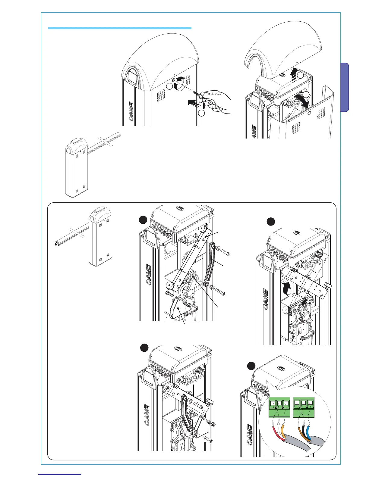
5.6 Installation of the Unit
- Remove the two screws
at the upper dome’s side
and lift it.
Insert the customised key
in the lock, turn it counter-
clockwise and remove the
hatch from the cabinet.
- The barrier is designed to be installed on the left of the gateway as
seen from inside.
Lever arm
Transmission rod
Spring securing bracket
Should installation on the right be
required, the direction of the bar’s
opening must be inverted. Proceed
in the following manner:
- remove the spring securing
bracket and the transmission rod
from the lever arm;
- loosen the motor support grub
screw;
- rotate the lever arm by 90°;
- Fix the spring securing bracket
and the transmission rod on the side
opposite that of lever arm;
- tighten the grub screw;
- invert the motor’s U-V phases and
the FA and FC endstop wires on the
control panel terminal.
Grub

 Loading...


