0.4 01/2012 © CAME cancelli automatici s.p.a. - The data and information reported in this installation manual are susceptible to change at any time and without obligation on CAME cancelli automatici s.p.a. to notify users.
ENGLISH
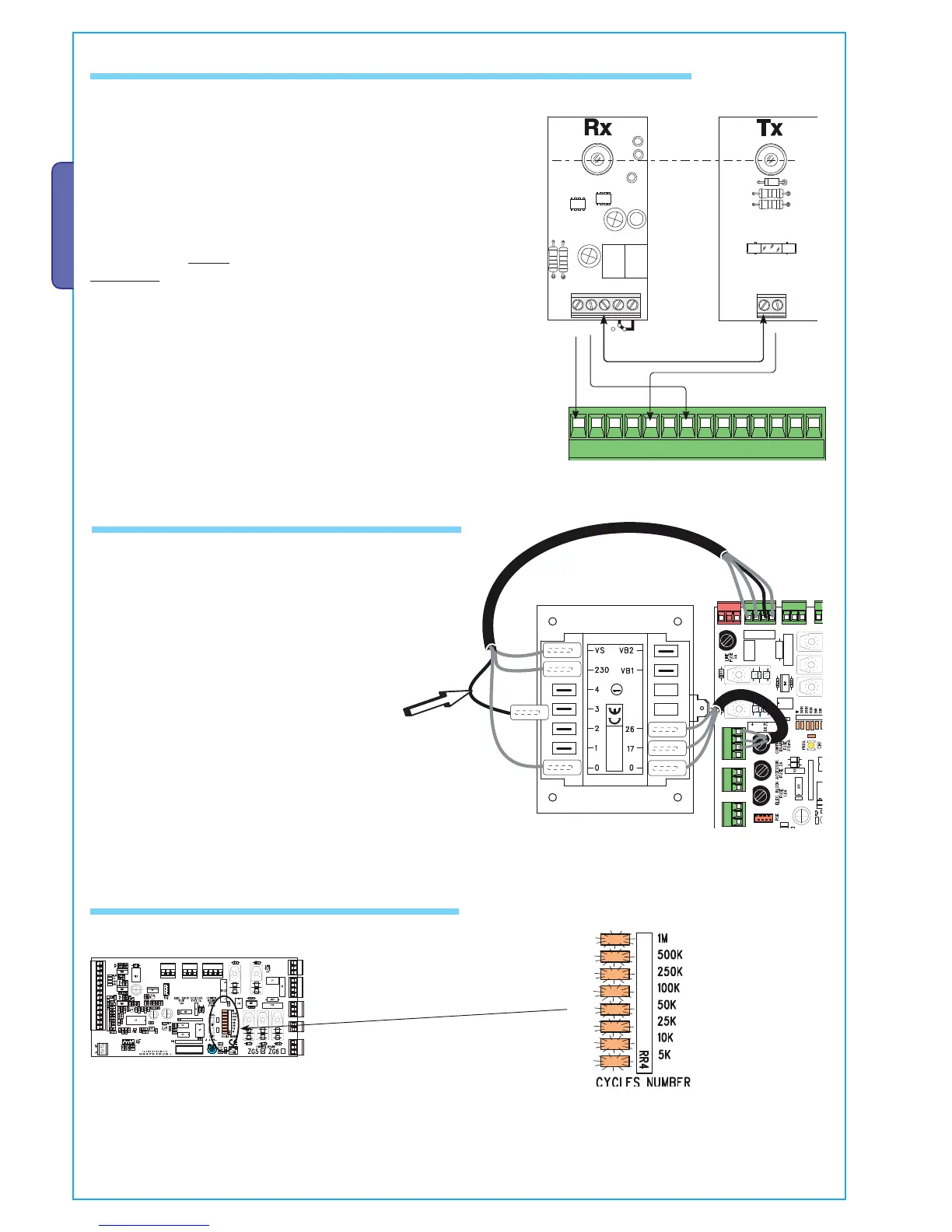
6.4 Motor torque limiter
6.3 Electrical connection to operate the photocells’ safety test
To manage the performance surge, position dip switches n. 1 and n. 3 to ON: all 8 led indicator lights on the performance counter
light up.
Reset Dipswitch 3 to OFF and leave Dipswitch 1 in the ON mode, if you want to activate the automatic closing function.
6.5 Managing operational surge
Allows the control assembly to check the e ciency of the safety de-
vices (photoelectric cells) after each opening or closing command.
A possible photoelectric cell malfunction is identifi ed with via LED
indicator fl ashing on the control panel, consequently cancelling any
remote control or pushbutton commands.
Electrical connection for safety test activation:
- photoelectric cell transmitters and receivers must be connected in
the following way (see scheme)
- turn dip-switch 8 to ON to carry out the test.
IMPORTANT:
When carrying out the safety test function, contacts N.C. if not used,
on the relative dip switches (see “functions selection” c. 6.9).
To vary the motor torque, move the shown faston (the one with
the black wire) to one of the 4 positions: 1 min – 4 max.

 Loading...


