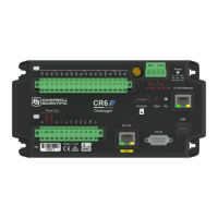
11.4.2 12V and SW12V power output terminals
12V, SW12-1, and SW12-2: Provide unregulated 12 VDC power with voltage equal to the Power
Input supply voltage. These are disabled when operating on USB power only. Voltage output is
0.3 VDC less than voltage at BAT terminals. The 12V terminal is limited to the current shown in
the previous table. Each SW12 terminal has a thermal-fuse hold-current limited to the values in
the following table.
SW12 current limits
Temperature (°C) Current Limit
1
(mA)
–40° 1600
0° 1290
20° 1100
50° 830
70° 640
85° 500
1
Thermal fuse hold current. Overload causes voltage drop.
Disconnect and let cool to reset. Operate at limit if the application
can tolerate some fluctuation.
11.4.3 U and C as power output
Operating at the current limit is OK if voltage fluctuation can be tolerated. Drive capacity is
determined by the logic level of the VDC supply and the output resistance (R
o
) of the U terminal.
It is expressed as: V
o
= 5V – (R
o
• I
o
), where V
o
is the drive limit, and I
o
is the current required by
the external device. For example: if a device requires the maximum current limit of 20 mA, on U1
(odd number terminal) the voltage level would reduce from 5V to 3.5V. To operate the same
device on U2 (even number terminal) the voltage would drop to 2.0V. Many 5V devices will not
operate correctly at 2.0V; so this device should be connected to an odd channel.
NOTE:
U terminals can be shorted to ground without damage.
l C Terminals:
o
Output Resistance (R
o
): 150 Ω
o
5 V Logic Level Drive Capacity: 10 mA @ 3.5 VDC; V
o
= 5 V - (150 Ω •I
o
)
o
3.3 V Logic Level Drive Capacity: 10 mA @ 1.8 VDC; V
o
= 3.3 V - (150 Ω •I
o
)
11. CR6 Specifications 214

 Loading...