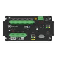
Table 2-1: Analog input terminal functions
U1 U2 U3 U4 U5 U6 U7 U8 U9 U10 U11 U12 RG
Single-Ended Voltage
ü ü ü ü ü ü ü ü ü ü ü ü
Differential Voltage H L H L H L H L H L H L
Ratiometric/Bridge
ü ü ü ü ü ü ü ü ü ü ü ü
Vibrating Wire (Static, VSPECT®)
ü ü ü ü ü ü
Vibrating Wire with Thermistor
ü ü ü
Thermistor
ü ü ü ü ü ü
Thermocouple
ü ü ü ü ü ü ü ü ü ü ü ü
Current Loop
ü
Period Average
ü ü ü ü ü ü ü ü ü ü ü ü
Table 2-2: Pulse counting terminal functions
U1 U2 U3 U4 U5 U6 U7 U8 U9 U10 U11 U12 C1-C4
Switch-Closure
ü ü ü ü ü ü ü ü ü ü ü ü ü
High Frequency
ü ü ü ü ü ü ü ü ü ü ü ü ü
Low-level Ac
ü ü ü ü ü ü
NOTE:
Conflicts can occur when a control port pair is used for different instructions (TimerInput
(), PulseCount(), SDI12Recorder(), WaitDigTrig()). For example, if C1 is used
for SDI12Recorder(), C2 cannot be used for TimerInput(), PulseCount(), or
WaitDigTrig().
Table 2-3: Analog output terminal functions
U1-U12
Switched Voltage Excitation
ü
Switched Current Excitation
ü
2. Wiring panel and terminal functions 6

 Loading...