TE-BBR Instruction and Operation Manual
System Components Arrangement
Control Unit
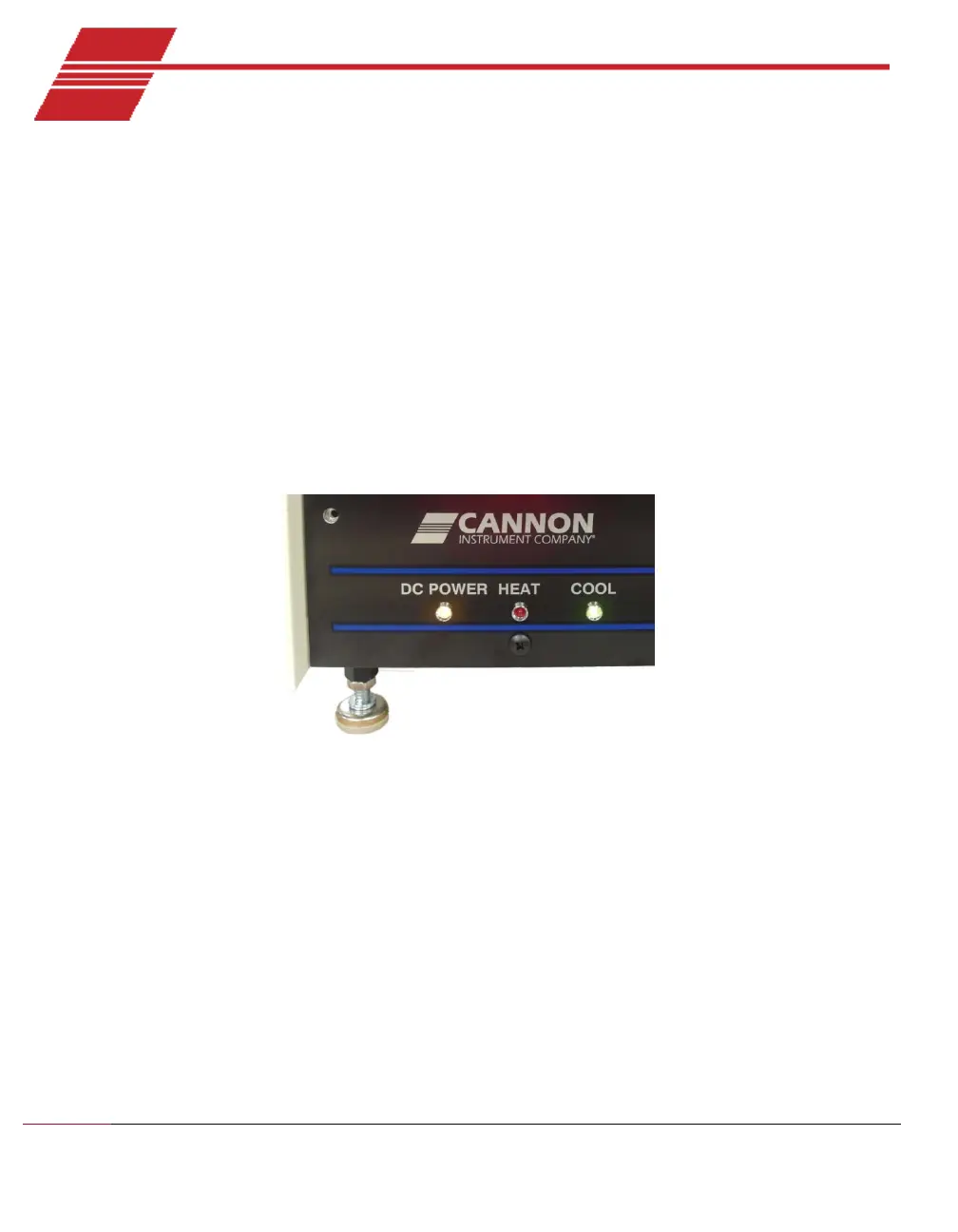
Locate the Control Unit and tilt it first to one side and then the other, extending the leveling legs as
you do so by turning them counter-clockwise. Refer to Figure 5. All four leveling legs should be
extended far enough to prevent the stirring motor shield at the very bottom of the unit from
contacting the surface of the supporting table/bench when the unit is upright. If this shield is
damaged, the stirring motor may be forced against the bottom of the tank, preventing rotation.
After extending the legs, set the Control Unit on a flat, level tabletop which has access to the floor
from the rear of the unit.
Figure 5: Levelling Legs
Stirring Bar Protection Sheet
Place the stirring bar protection sheet in the bottom of the bath.
Stirring Bar
Place the cross-shaped stirring bar on the stainless steel plate in the center of the bath. Place the
stirring bar cover grid over the bar and make sure that the grid does not impede rotation of the
stirring bar. When the bath is functioning, the speed of the stirring bar is controlled magnetically
using the speed control dial on the left rear panel (as viewed from the rear) of the Control Unit. Refer
to Figure 6.