CANNON Instrument Company | Troubleshooting
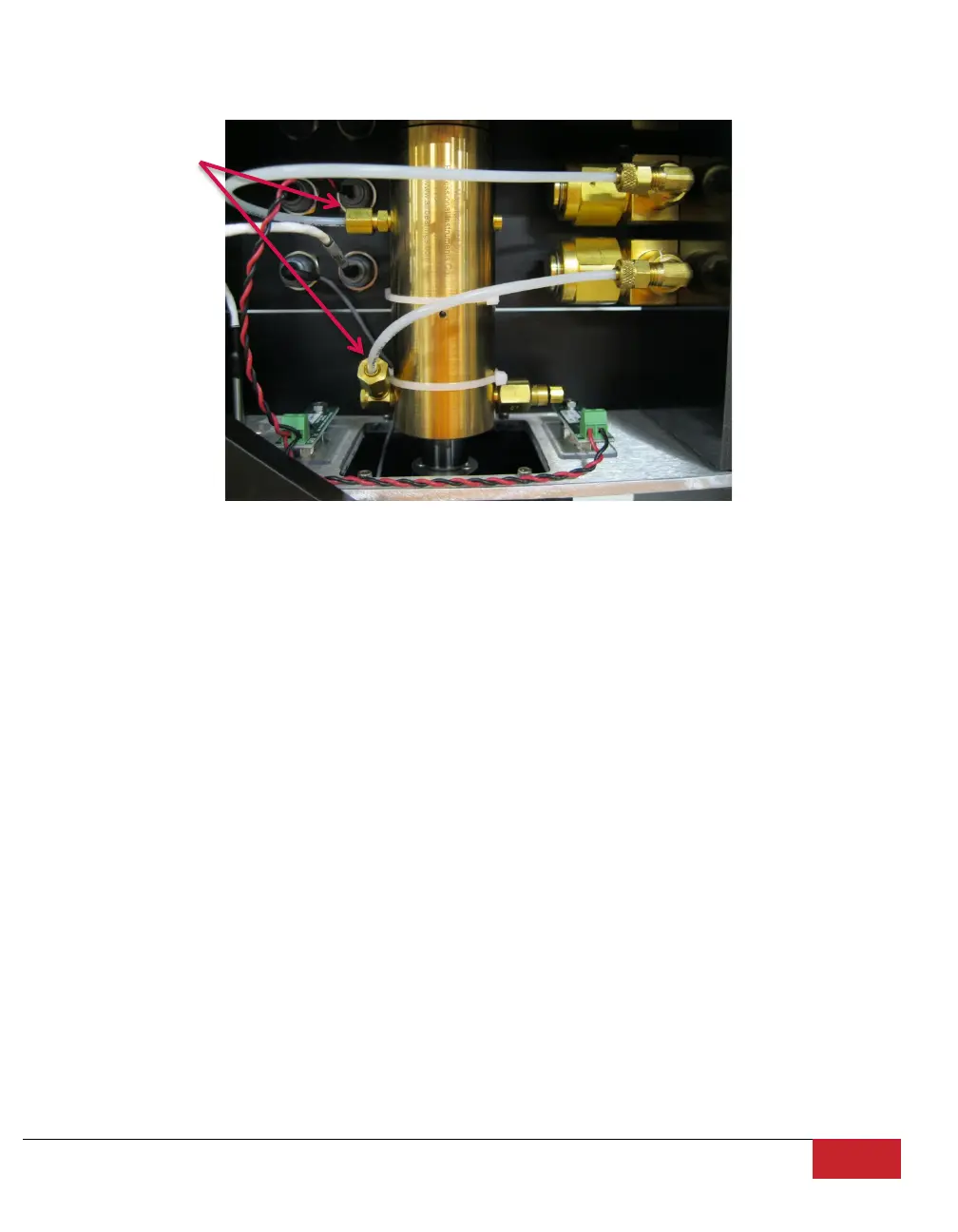
4. Locate the upper and lower air line to the load cylinder as shown in Figure 29.
Figure 29: Load Cylinder Air Line Connections
5. Using a wrench, disconnect the upper and lower air line at the load cylinder.
6. Restore power to the TE-BBR and permit air to blow through the unattached air lines for two or
three minutes to clear the lines of any contaminants.
7. Use the ZERO regulator on the Control Unit to adjust the ZERO pressure to 0 psi.
8. Use the LINE regulator on the Control Unit to adjust the LINE pressure to 0 psi.
9. Reconnect the upper air line, tightening the connection finger tight; tighten an additional quarter-
turn with the wrench.
10. Introduce a small quantity of petroleum-based solvent to the load cylinder around the air bearing
shaft where the shaft passes through the horizontal support frame beneath the load platform.
11. Continue to apply small amounts of solvent while manually raising and lowering the load platform to
encourage distribution of solvent between the shaft and the wall of the load cylinder. Allow the
solvent to remain in the cylinder for several minutes.
12. Use the LINE regulator on the Control Unit to restore normal line pressure. Solvent will be forced
out the top and bottom of the load cylinder.
13. Gently wipe away excess solvent from the shaft and load cylinder with an absorbent paper towel.
Continue this air-drying procedure until all solvent has been removed from the air bearing.