CANNON Instrument Company | Appendix 3 – Technical Note 0611091
6. Set the two interchangeable replacement beam supports/adapters on the base of the Load Frame in
place of the beam supports previously removed.
7. Secure the new beam support/adapters to the Load Frame using the screws/washers previously
removed, in the same orientation as the previous supports. The groove for temperature probe
should be oriented toward the rear of the Load Frame.
8. Ensure that the thin beam assembly and the thick beam can fit in the cut-out area on the (lower)
Crack Seal beam support. Refer to Figure 36. If they cannot be seated properly, loosen the screws
securing the beam support to the Load Frame and take advantage of any "play" to readjust the
position of the supports until the beam(s) can be correctly positioned.
Figure 36: Crack Seal Option Installation (note probe location and cut-out area for beam placement)
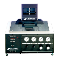
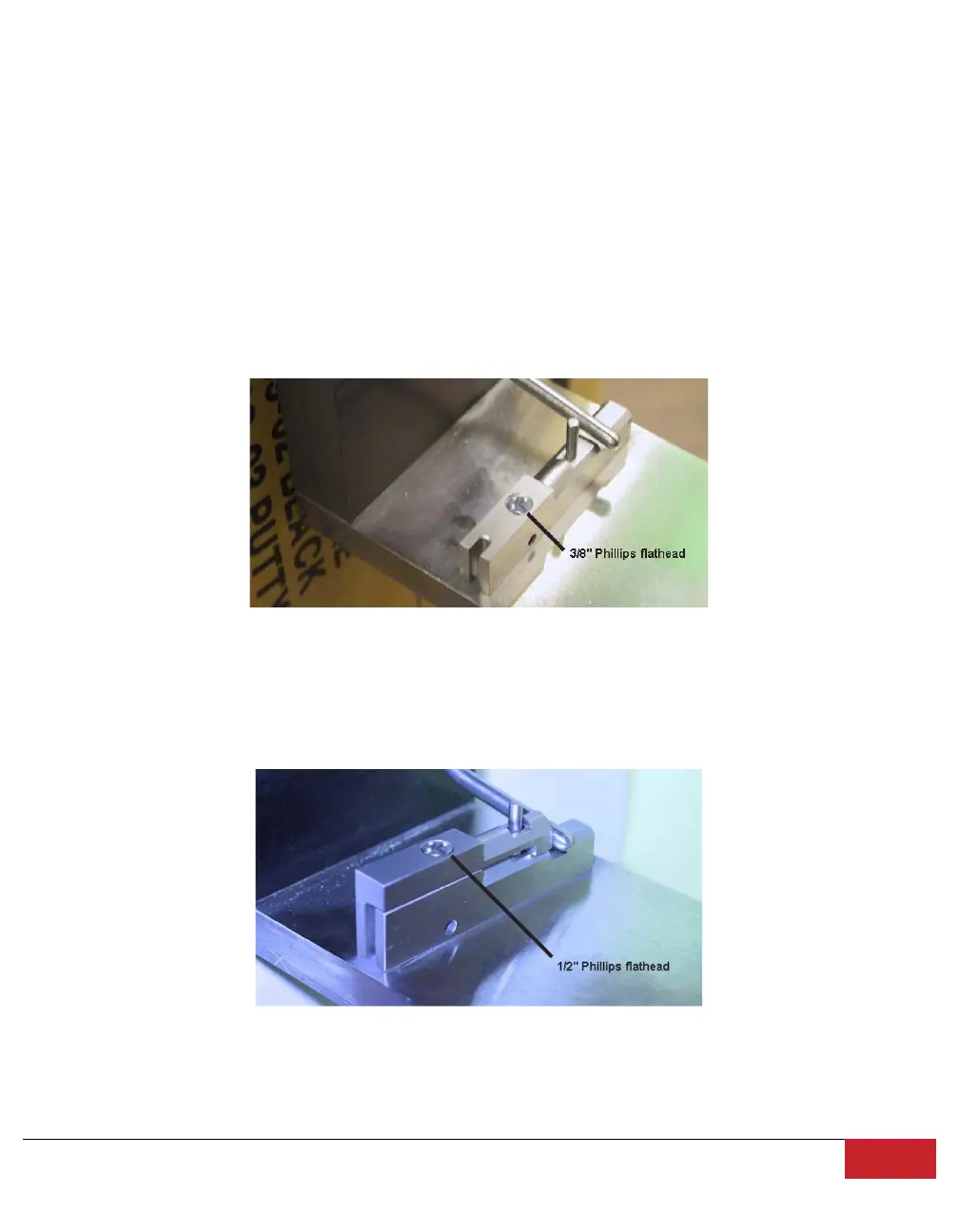
9. If necessary/desired, secure the beam support adapter (for asphalt beam testing) to the beam
support using the ½” flathead Phillips screws provided. Otherwise, install the shorter 3/8" Phillips
screws to the bottom beam support to prevent debris from plugging the hole. Refer to Figure 37.
Figure 37: Crack Seal Option Installation with Adaptor for Normal Asphalt Beam BBR Operation