CANNON Instrument Company | Electrical Connections
Electrical Connections
Load/Control Unit Connections
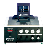
There are four color-coded electrical receptacles on the rear panel of the Load Frame. Using the
cables supplied, connect the Load Frame receptacles to those of corresponding color on the rear
panel of the Control Unit. Refer to Figure 8 and Figure 9.
Figure 8: Electrical Connections – Load Frame Figure 9: Electrical Connections – Control Unit
Control Unit – Heat Exchanger Connections
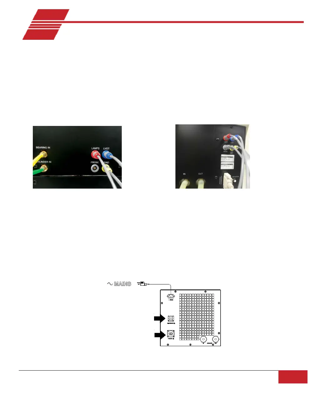
Make certain the power switch on the TE-BBR is in the OFF (O) position. Then connect the two large
power cables between the air/water heat exchanger and the rear panel of the Control Unit. Refer to
Figure 10. The connections are keyed and will only fit one way. Insert the MAINS power cord into
the MAINS outlet on the Air/Water Heat Exchanger and plug the other end into a suitable receptacle
matching the electrical specifications on the rear of the unit.
Figure 10: Air/Water Heat Exchanger Power Connections