COPYRIGHT © 1999 CANON INC. CANON DADF-B1 REV.0 APR. 1999 PRINTED IN JAPAN (IMPRIME AU JAPON)
2-3
CHAPTER 2 BASIC OPERATION
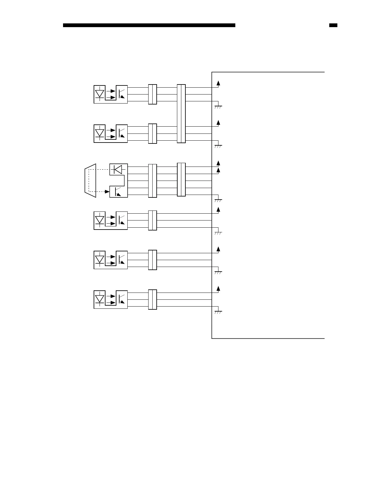
Figure 2-103
2. Inputs to the ADF Controller PCB (2/2)
J1107
J107
SR4
3
1
2
6
4
5
J7A-1
+
5V
J6FA-3
EENT
J6FA-2
1
3
2
4
6
5
3
1
2
3
1
2
3
1
2
J108
SR5
3
1
2
J7A-4
+
5V
J6FA-6
EREG
J6FA-5
3
1
2
3
1
2
J109
SR6
J7B-1
+
5V
J6FA-3
OPEN*
J6FA-2
1
2
3
1
2
3
J110
SR7
J7B-6
+
5V
J6FA-5
EMCK
J6FA-4
3
1
2
3
1
2
J111
SR8
J7B-7
+
5V
J6FA-9
The asterisk (*) indicates that the signal turns on
when ’0’ (low active).
When the reversal delivery unit cover
is opened, ’0’.
(When the light-blocking plate is at
the sensor.)
While the reversing delivery motor is
rotating, alternates between ’1’ and ’0’.
When the ADF is opened, ’0’.
(When the light-blocking plate is
not at the sensor.)
When an original blocks the sensor, ’0’.
When an original is detected, ’1’.
(When the light-blocking plate is at
the sensor.)
When an original is detected, ’1’.
(When the light-blocking plate is at
the sensor.)
J6FA-8
3
4
1
2
5
3
2
5
4
1
3
2
1
5
4
J103
U505
3
2
5
4
1
J7B-10
J6FA-9
J6FA-7
J6FA-8
J6FA-11
+
5V
+
24V
TURN
TULED
J501 J502
ADF controller PCB
Reversal delivery inlet
sensor
Reversal delivery
registration sensor/delivery sensor
Reversal outlet sensor
ADF open/closed sensor
Reversal delivery motor
clock sensor
Reversal delivery
unit cover sensor
 Loading...