COPYRIGHT © 1999 CANON INC. CANON DADF-B1 REV.0 APR. 1999 PRINTED IN JAPAN (IMPRIME AU JAPON)
3-1
CHAPTER 3 MECHANICAL SYSTEM
I. BASIC CONSTRUCTION
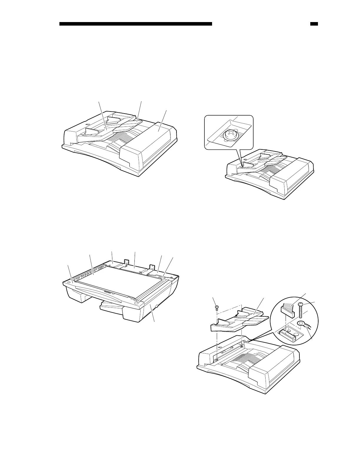
A. External Covers
Figure 3-101
[1] Original tray
[2] Auxiliary tray
[3] Reversal delivery unit cover
Figure 3-102
[1] Front cover
[2] Rear cover 1
[3] Rear cover 2
[4] ADF controller cover
[5] Timing belt cover
[6] Feed belt
[7] Pickup unit cover
Remove the appropriate covers as follows
when cleaning, inspecting, or repairing the
inside of the machine.
1. Removing the Original Tray
1) Mark the position of the original tray in
advance (by referring to the graduations
under the fixing screw).
Figure 3-103
2) Remove the two fixing screws [1], and
shift the original tray [2] to the front.
3) Remove the screw [4], and disconnect the
connector [5]; then, detach the grounding
wire [3].
4) Detach the original tray.
Figure 3-104
[1]
[2]
[3]
[1]
[6]
[2]
[4]
[3]
[5]
[7]
[1]
[2]
[5]
[4]
[3]