CHAPTER 3 MECHANICAL SYSTEM
3-18
COPYRIGHT © 1999 CANON INC. CANON DADF-B1 REV.0 APR. 1999 PRINTED IN JAPAN (IMPRIME AU JAPON)
VI. SENSORS
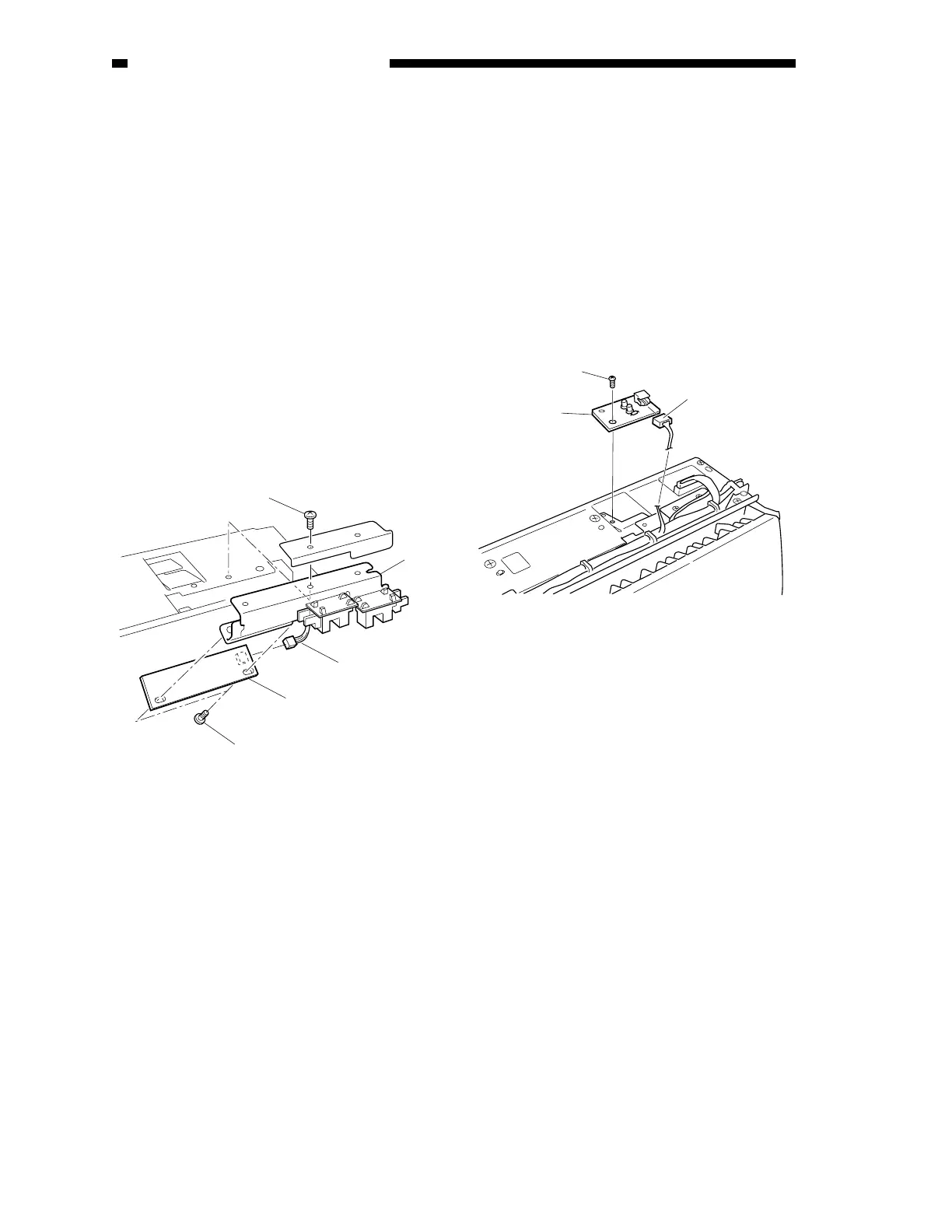
A. Removing the Original Set
Sensor PCB (U503)
1) Remove the pickup unit. (See A.
“Removing the Pickup Unit.” under II.
“Drive System.”)
2) Shift the harness guide. (See Figure 3-
302.)
3) Remove the mounting screw [2], and
detach the mounting stay [1] of the
original set sensor PCB.
4) Disconnect the connector [5].
5) Remove the two mounting screws [4], and
detach the original set sensor PCB [3].
Figure 3-401
B. Removing the Original Set
Indicator LED PCB
1) Remove the pickup unit. (See A.
“Removing the Pickup Unit” under II.
“Drive System.”)
2) Disconnect the connector [3].
3) Remove the mounting screw [2], and
detach the original set indicator LED PCB
[1].
Figure 3-402
[1]
[2]
[4]
[3]
[5]
[2]
[3]
[1]
 Loading...