CHAPTER 5 TOROUBLESHOOTING
5-4
COPYRIGHT
©
1999 CANON INC. CANON DADF-B1 REV.0 APR. 1999 PRINTED IN JAPAN (IMPRIME AU JAPON)
B. Electrical System
1 When Replacing the Major Parts
Table 5-103
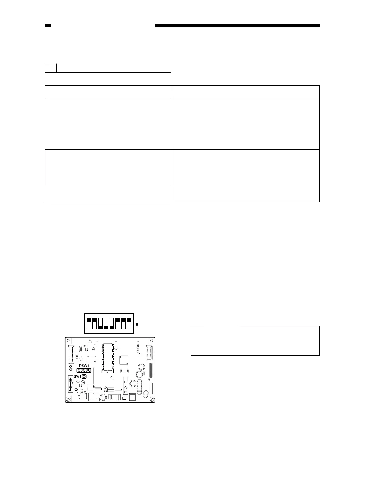
2 EEPROM Initialization
1) Remove the ADF controller cover, and
shift bits 4, 5, and 6 of the DIP switch
(DSW1) on the ADF controller PCB to
ON.
2) Open the pickup unit cover.
Figure 5-107
3) While holding down the push switch, turn
off and then on the copier.
This will initialize the backup data of the
EEPROM.
4) Check to make sure that LED2 is on.
5) Close the pickup unit cover, and shift all
bits of the DIP switch (DSW1) to OFF.
6) Turn off the copier; then, turn it on once
again.
Caution:
If you have replaced the ADF controller
PCB once again, be user to initialize the
EEPROM first.
Major parts Work
ADF controller PCB 1. EEPROM initialization
2. Original tray width adjustment
(A/B-configuration, inch-configuration)
3. Sensor level adjustment
4. Registration position adjustment
5. Duplexing registration adjustment
Last original sensor (U504) 1. Sensor level adjustment
Original set sensor (U503)
Pre-registration sensor (U502)
Reversal outlet sensor (U505)
Original width detecting volume (U508) 1. Original pickup tray width adjustment
O
F
F
1
2
3
4
5
6
7
8
ON
 Loading...