CHAPTER 2 BASIC OPERATION
2-4
COPYRIGHT © 1999 CANON INC. CANON DADF-B1 REV.0 APR. 1999 PRINTED IN JAPAN (IMPRIME AU JAPON)
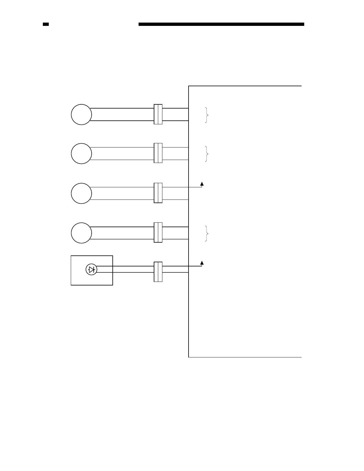
Figure 2-104
C. Outputs from the ADF Controller PCB
1. Outputs from the ADF Controller PCB (1/1)
J104
M1
M
M
M
BK
1
2
J5-1
J6FA-2
1
2
J104
1
2
J5-3
J6FA-4
1
2
J112
1
2
J5-5
J6FAJ5-6
1
2
J112
1
2
J9-1
J6FA-2
1
2
M2
+
24V
+5
V
M3
BK1
U507
BK
J701
2
1
J6B-1
J6FA-2
2
1
EJM2
OGLED
SPM1
SPM2
FDM1
FDM2
EJM1
ADF controller PCB
Separation motor
Feed motor
Feed motor brake
Reversal delivery motor
Original Set indicator (LED)
When ’0’, the Original Set indicator
turns on.
See "Controlling the Reversal
Delivery Motor (M3)" on p. 2-29.
When ’0’, the brake (BK1) turns on.
See "Controlling the
Feed Motor (M2)" on p. 2-21.
See "Controlling the
Separation Motor (M1)" on p. 2-16.
 Loading...