CHAPTER 2 BASIC OPERATION
2-50
COPYRIGHT © 1999 CANON INC. CANON DADF-B1 REV.0 APR. 1999 PRINTED IN JAPAN (IMPRIME AU JAPON)
I. Power Supply
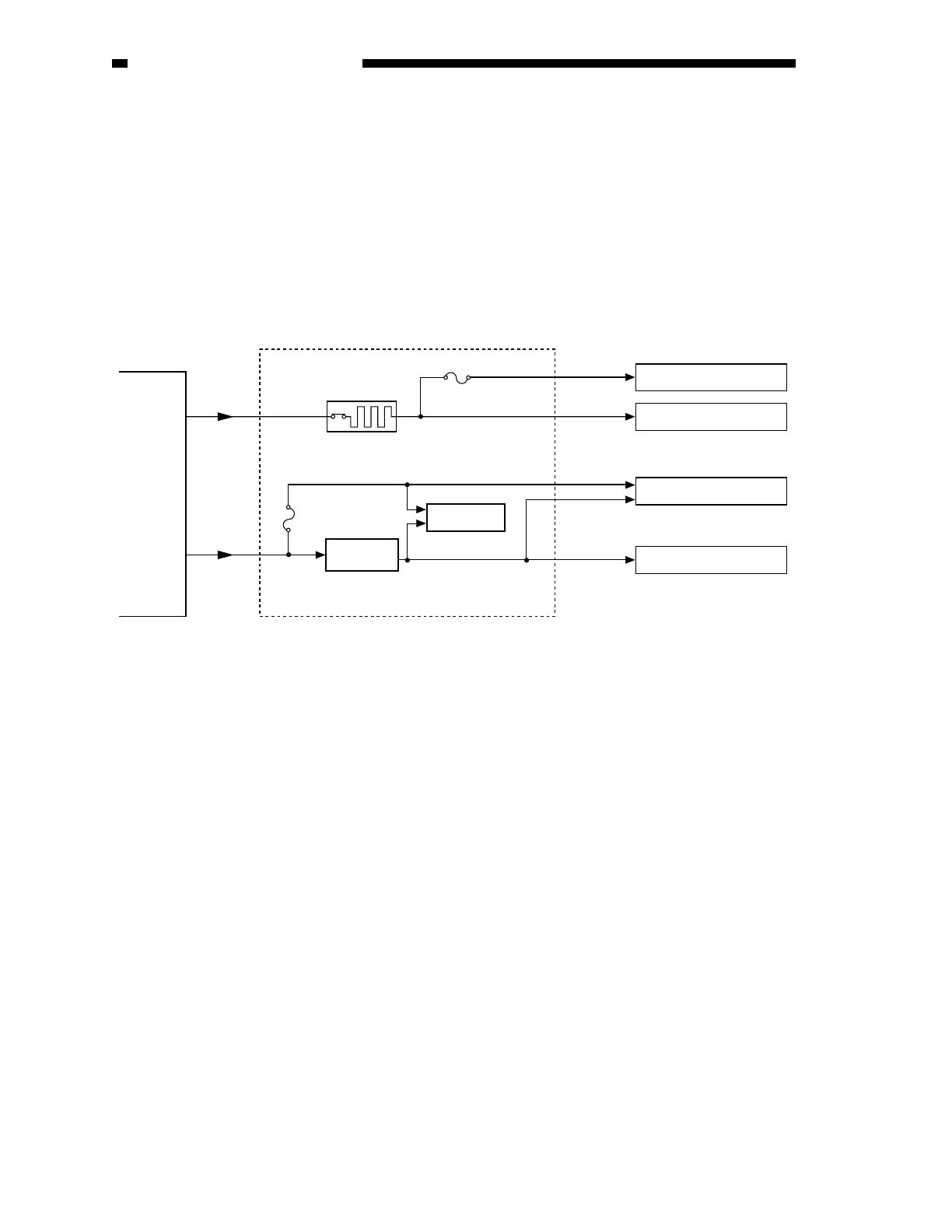
The following figure shows an outline of the power supply system.
The ADF is supplied with two channels of 24 V power by the copier. One line (J2) runs through
a circuit breaker (CB1) to reach various loads; the circuit breaker is designed to turn on in response to
an overcurrent threatening the ADF’s circuitry. The other line (J1F) caries power which is converted
into 5 V by a regulator (Q17) and is used by logic and sensor systems; a fuse resistor (FU1, FU2) is
provided to cut off the power in response to an overcurrent in the circuit, thereby protecting the
circuit.
24V
24V
5V
5V
5V
24V
J1
J2
Copier ADF controller PCB
Break
Motor
Sensor
Sensor
Fuse resistor
(FU1)
Fuse resistor
(FU2)
Regulator
IC (Q17)
Logic
Circuit breaker
(CB1)
Figure 2-281