COPYRIGHT
©
1999 CANON INC. CANON DADF-B1 REV.0 APR. 1999 PRINTED IN JAPAN (IMPRIME AU JAPON)
5-9
CHAPTER 5 TROUBLESHOOTING
II. TROUBLESHOOTING
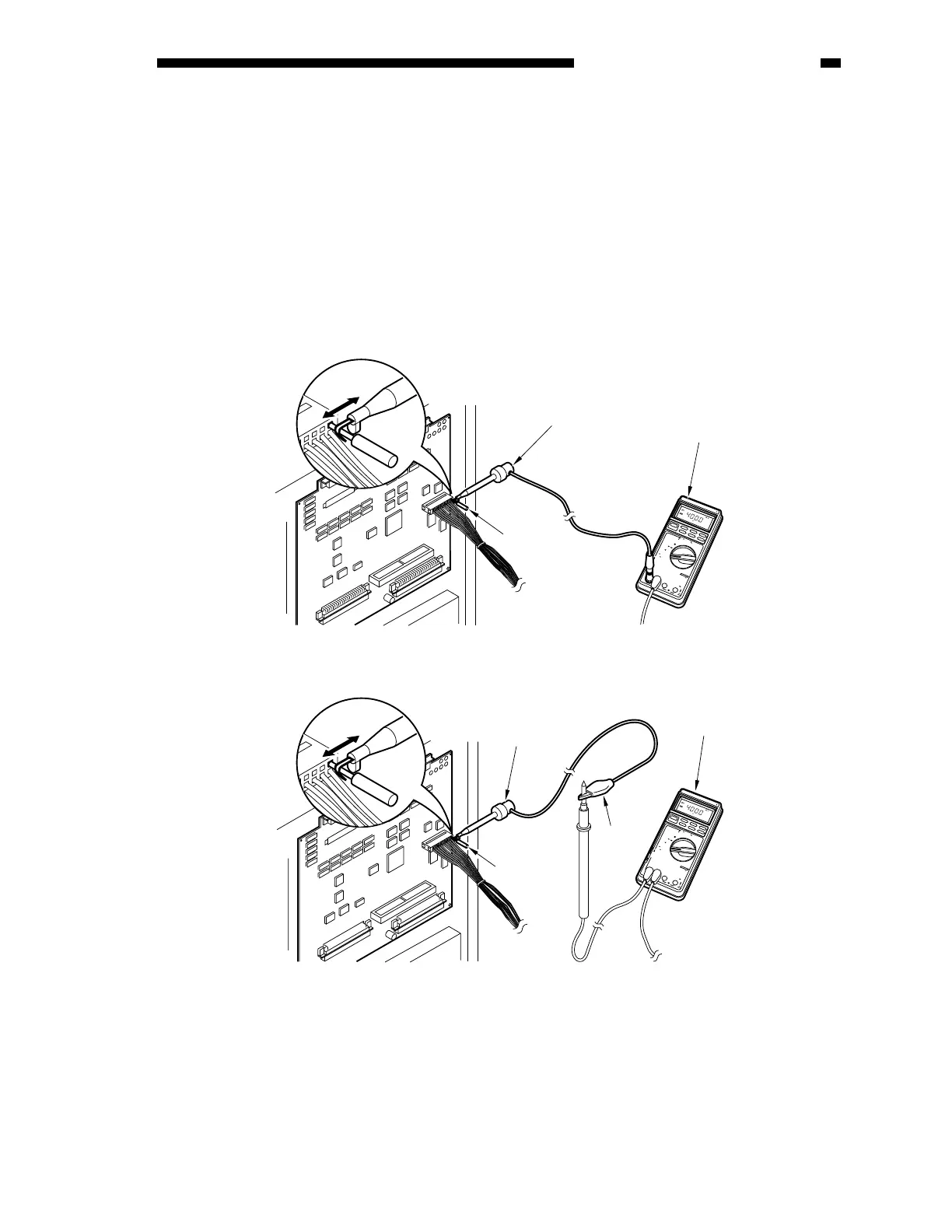
You cannot directly fit the probes of a meter into the connectors (J6, J7) of the PCB of the ADF.
(The connectors are designed in a special way to ensure good connection.) If you must check the
connector J6 or J7 on the ADF controller PCB when performing troubleshooting work, be sure to
obtain a probe extension (FY9-3038-000, FY9-3039-000).
1) Set the meter to the DC range.
2) Connect the probe of the meter to GND (0 VDC) on the ADF controller PCB.
3) Set the probe extension as follows:
Figure 5-201
7
5
3
7
04
D
I
G
I
T
A
L
M
U
L
T
I
M
E
T
E
R
YOKOGAWA
P
O
W
E
R
O
P
E
N
T
E
R
M
I
N
A
L
S
H
U
T
T
E
R
20
k
H
z
1
0
A
C
O
M
V
・
Ω
・
m
A
・
μ
A
1
0
A
m
A
0
2
4
2
R
E
L
/
%
A
V
G
S
E
L
E
C
T
R
A
N
G
E
M
IN
/M
A
X
D
A
T
A
-
H
4
D
・
H
−
+
m
V
m
V
±
+
〜
/
L
o
H
z
/
r
p
m
/
〜
/
A
D
P
/
K
℃
V
〜
V
H
z
/
℃
Ω
μ
A
F
U
S
E
D
F
U
S
E
D
1
0
0
0
V
M
A
X
!
T
R
U
E
R
M
S
0
.
1
%
V
/
〜
/
H
z
7
5
3
7
04
D
I
G
I
T
A
L
M
U
L
T
I
M
E
T
E
R
YOKOGAWA
P
O
W
E
R
O
P
E
N
T
E
R
M
I
N
A
L
S
H
U
T
T
E
R
20
k
H
z
1
0
A
C
O
M
V
・
Ω
・
m
A
・
μ
A
1
0
A
m
A
0
2
4
2
R
E
L
/
%
A
V
G
S
E
L
E
C
T
R
A
N
G
E
M
IN
/M
A
X
D
A
T
A
-H
4
D
・
H
−
+
m
V
m
V
±
+
〜
/
L
o
H
z
/
r
p
m
/
〜
/
A
D
P
/
K
℃
V
〜
V
H
z
/
℃
Ω
μ
A
F
U
S
E
D
F
U
S
E
D
1
0
0
0
V
M
A
X
!
T
R
U
E
R
M
S
0
.
1
%
V
/
〜
/
H
z
FY9-2004-000
FY9-2003-000
[ Method 1 ]
[
Connection 2 ]
Grasp the
pin
Meter
Grasp the
pin
Probe extension
(FY9-3038)
Meter
Clip
Probe
extension
 Loading...