CHAPTER 2 BASIC OPERATION
2-16
COPYRIGHT © 1999 CANON INC. CANON DADF-B1 REV.0 APR. 1999 PRINTED IN JAPAN (IMPRIME AU JAPON)
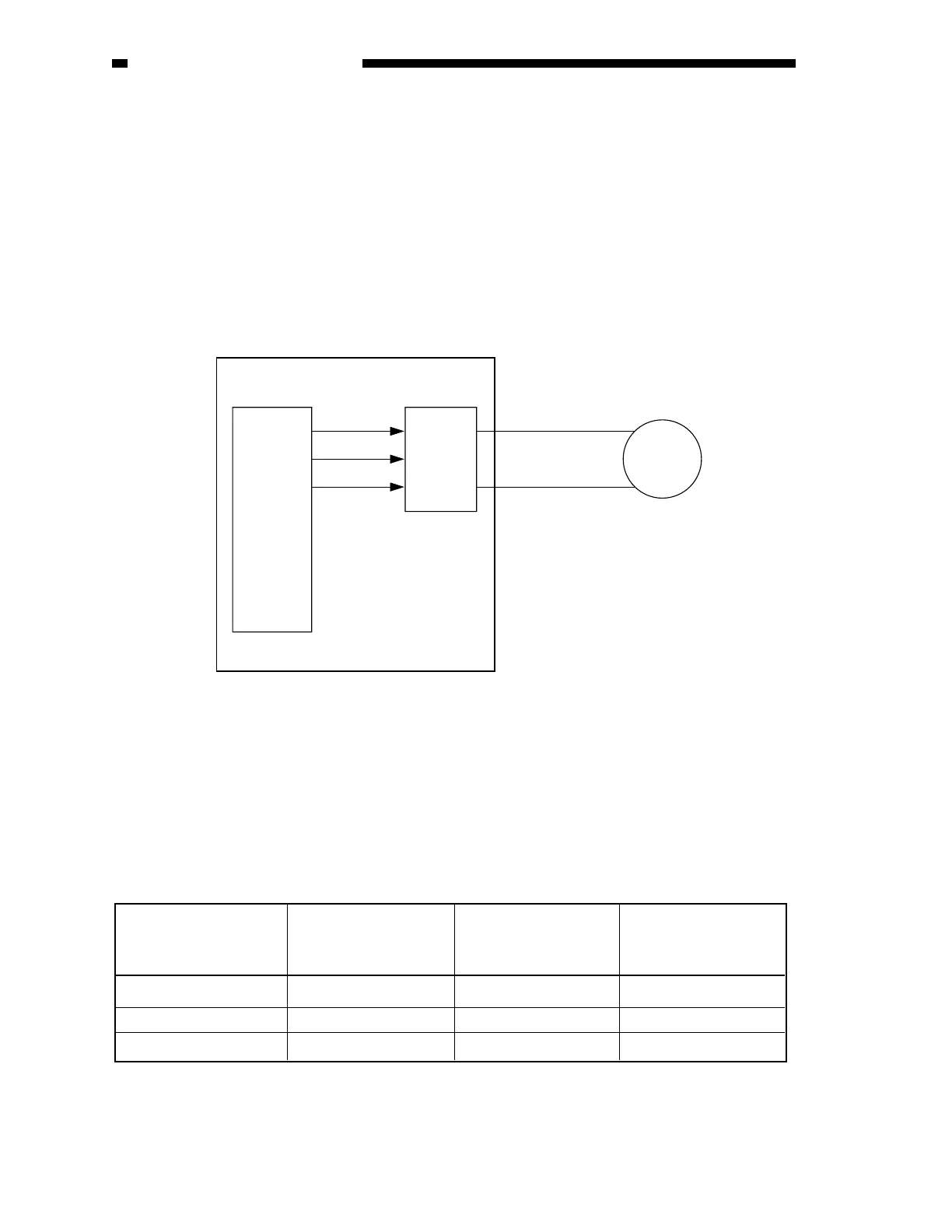
4. Controlling the Separation Motor (M1)
Figure 2-219 is a diagram of the control circuit used for the separtion motor (M1).
The separation motor is a DC motor, and the CPU (Q1) on the ADF controller PCB sends the
separation motor rotation speed control signal (SMPWM) and the separation motor rotation direction
signal (SMFWD, SMREV) to the drive circuit, which in response drives the separation motor.
The control circuit does no possess a circuit designed to communicate the state of the separation
motor back to the CPU (Q1). The rotation speed control signal (SMPWM) remains the same at all
times, and no correction is made even when changes occur in the rotation speed of the separation
motor because of external force.
The relationship between the separation motor rotation speed control signal (SMPWM), the
separation motor rotation direction signal (SMFWD, SMREV), and the separation motor is as shown
in Table 2-204.
Q1
CPU
M1
SMPWM J5F-1
J5F-2
SMFWD
SMREV
Drive
circuit
ADF controller PCB
Separation
motor
Figure 2-219
Stops
Rotates CW
Rotates CCW
’0’
’1’
’0’
’0’
’0’
’1’
’0’
’1’
’1’
Separation motor rotation
speed control signal
(SMPWM)
Separation motor rotation
direction signal
(SMFWD)
Separation motor rotation
direction signal
(SMREV)
Separation motor
operation
Table 2-204
 Loading...