Chapter 6
6-1
6.1 Troubleshooting
6.1.1 Outline
6.1.1.1 Outline of Troubleshooting
0013-1940
1. Outline
Troubles subject to troubleshooting are classified into those shown on the display (warning, error, and service call) and those not shown on the display.
The code of warning and error is shown by combining alphanumeric characters of eight digits and four digits.
The code of service call error is shown by the initial character of "E" and combining alphanumeric characters of three digits and four digits.
No code number is displayed when a warning occurs. Selecting [SERVICE MODE] > [DISPLAY] > [WARNING] in service mode allows you to check the warning
log.
2. Precautions for Troubleshooting
1) Check the environmental conditions and the media used for printing.
2) Before performing troubleshooting, make sure that all connectors and cables are connected properly.
3) When servicing the printer with the external cover removed and the AC power supplied, be extremely careful to avoid electric shock and shorting electrical
devices.
4) In the following sections, the troubleshooting steps are described such that the component related to the most probable cause of the problem will be repaired or
replaced first, being followed by components with less problem probability. If multiple components have the same problem probability, the steps are described
beginning with the easiest one.
After performing each step, check to see if the problem has been resolved by making test prints. If the problem persists, proceed to the next step.
5) After completion of the troubleshooting, check that all connectors and cables have been reconnected and screws have been tightened firmly.
6) Whenever you have performed replacement or repair services, make test prints to check whether the problem has been resolved.
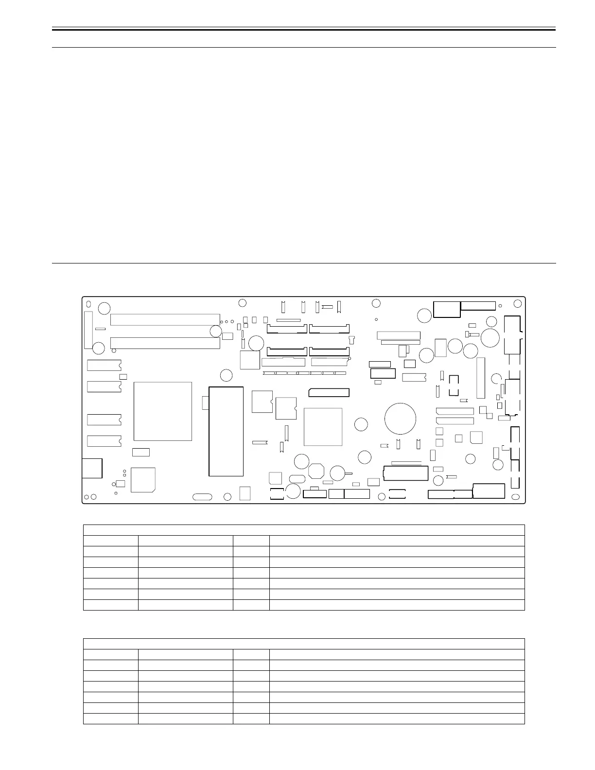
6.2 Location of Connectors and Pin Arrangement
6.2.1 Main controller PCB
0025-0536
F-6-1
T-6-1
T-6-2
J1001
Pin Number Signal name IN/OUT Function
1 VBUS IN USB VBUS(+5V)
2 D- IN/OUT USB data(-)
3 D+ IN/OUT USB data(+)
4 AGND - USB GND
5 FGND - GND (Connector shell)
6 FGND - GND (Connector shell)
J1102
Pin Number Signal name IN/OUT Function
1 GND - GND
2 GND - GND
3 GND - GND
4 +3.3V OUT Power supply(+3.3V)
5 +3.3V OUT Power supply(+3.3V)
6 +3.3V OUT Power supply(+3.3V)
1
1
1
1
1
1
1
J1001
J1201
J3301
J3002
J3201
J2502
J2702
J1102
J2701
J3501 J3601
J3502 J3602
J3401
J3150
J3001
J3003
J1801
J2801
J2501
J2601
J2402
J3910
1
1
1
1
1
A1
B1
1
1
B1
A1
11
A1
B1
1
1
1
1
1
J1202
 Loading...