Chapter 6
6-12
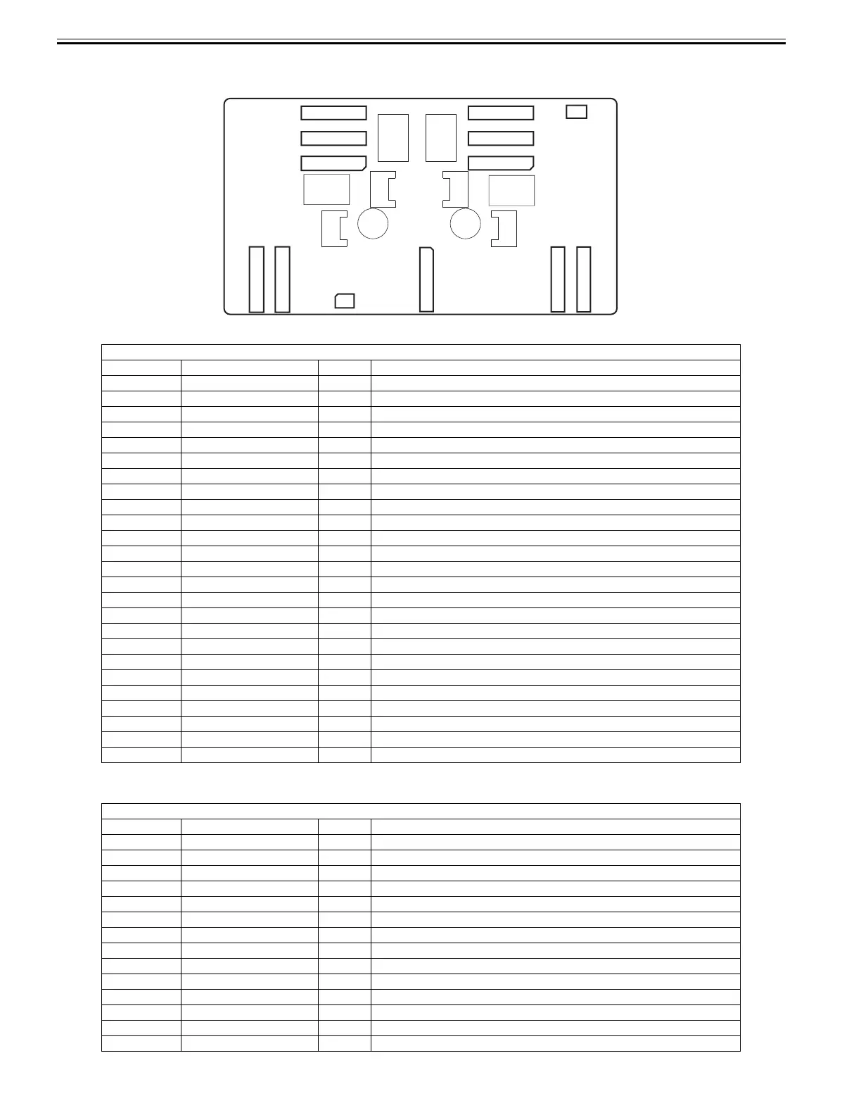
6.2.2 Carriage relay PCB
0025-0539
F-6-2
T-6-24
T-6-25
J101
Pin Number Signal name IN/OUT Function
1 VMGND - GND
2 VMGND - GND
3 VMGND - GND
4 VMGND - GND
5 VM OUT Power supply(+32V)
6 VM OUT Power supply(+32V)
7 VM OUT Power supply(+32V)
8 VM OUT Power supply(+32V)
9 VM OUT Power supply(+32V)
10 VM OUT Power supply(+32V)
11 VM OUT Power supply(+32V)
12 VM OUT Power supply(+32V)
13 SNS5V OUT Power supply(+5V)
14 SNS5V OUT Power supply(+5V)
15 GND - GND
16 +3.3V OUT Power supply(+3.3V)
17 +3.3V OUT Power supply(+3.3V)
18 GND - GND
19 VM_26V OUT Power supply(+26V)
20 VMGND - GND
21 VH_MONI3 IN VH controll signal 3
22 VH_MONI1 IN VH controll signal 1
23 VMGND - GND
24 VMGND - GND
25 VMGND - GND
J102
Pin Number Signal name IN/OUT Function
1GND -GND
2GND -GND
3 /H1-C-HE-4_B OUT Head(R) heat enable signal 4(C)
4GND -GND
5 H1-B-DATA-3-OD_B OUT Odd head(R) data signal 1(B)
6GND -GND
7 H1-B-DATA-2-OD_B OUT Odd head(R) data signal 2(B)
8GND -GND
9 PWLED4_ON OUT Multi sensor LED4 drive signal
10 MLT_SENS_2IN IN Multi sensor signal 2
11 MLT_SENS_1IN IN Multi sensor signal 1
12 H3V_ON OUT Power supply
13 PWLED3_ON OUT Multi sensor LED3 drive signal
14 PWLED1_ON OUT Multi sensor LED1 drive signal
J105 J104 J101 J102 J103
J201
J703
J702
J701
J803
J802
J801
1
1
1
1
1
1
11
1
111
J105 J104 J101 J102 J103
J201
J703
J702
J701
J803
J802
J801
1
1
1
1
1
1
11
1
111
1
J202
 Loading...