Chapter 2
2-41
2.4.4 Motor Driver
2.4.4.1 Roll feed unit PCB components
0013-4323
F-2-40
a) Driver IC (IC1)
Roll motor drive function
This function controls the roll motor based on the control signals from the main controller.
Sensor relay function
This function relays the input signals from the roll cam sensor and roll media sensor to the main controller PCB.
2.4.5 Maintenance Cartridge Relay PCB
2.4.5.1 Maintenance cartridge relay PCB components
0013-5143
F-2-41
a) EEPROM (IC1)
The 128-KB EEPROM stores all information written to the EEPROM on the main controller PCB.
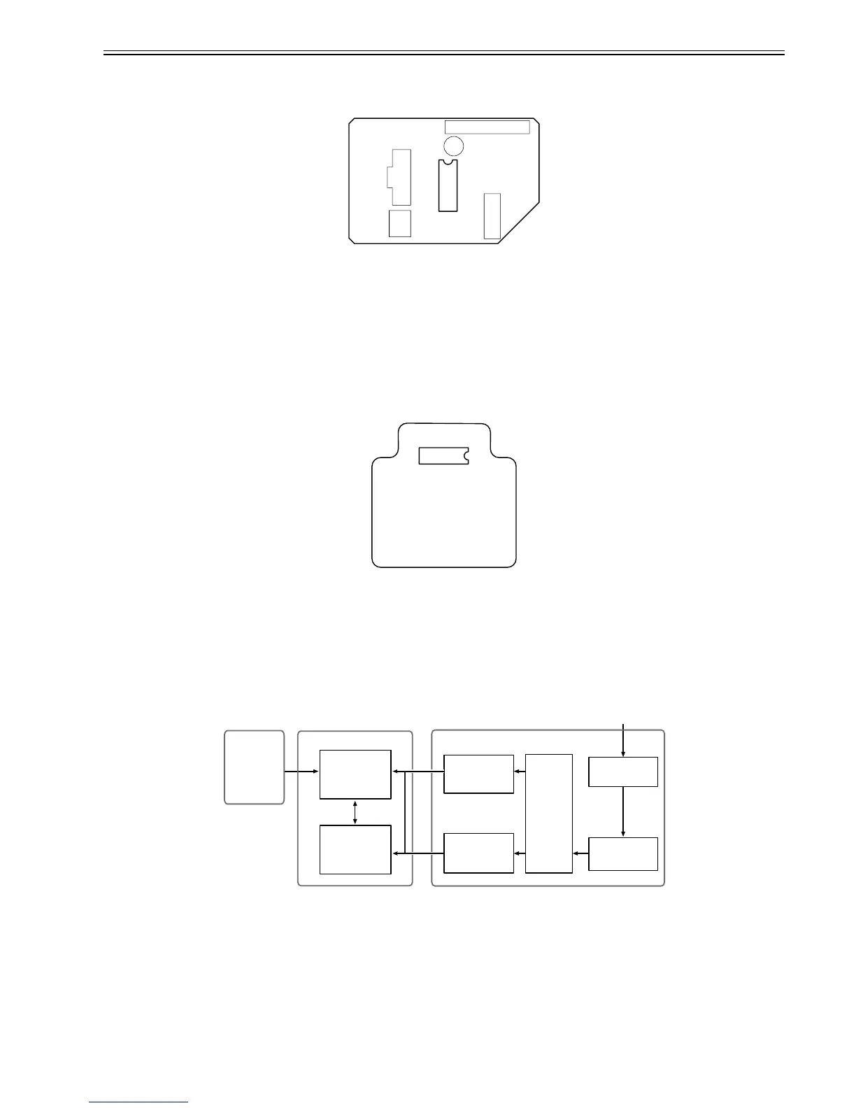
2.4.6 Power Supply
2.4.6.1 Power supply block diagram
0013-4333
F-2-42
The power supply converts AC voltages ranging from 100 V to 240 V from the AC inlet to DC voltages for driving the ICs, motor, and others.
The voltage generator circuits include the +26 V generation circuit for driving motors, fans, and sensors and a +21.5 V generator circuit for driving sensors, heads,
logic circuits, and others.
When the power is turned off, +26 V and +21.5 V are reduced to about 12 V and 9 V respectively (power save mode).
Power ON/OFF operation is controlled by the main controller PCB.
IC 1
IC 1
Operation panel
Transformer
DC power supply
control circuit
+21.5V
generation circuit
+26V
generation circuit
POWER ON
Rectifying circuit
Noize filter circuit
AC inlet
100V to 240V
Power supplyMain controller PCB
+5V/+3.3V
generation circuit