Chapter 2
2-18
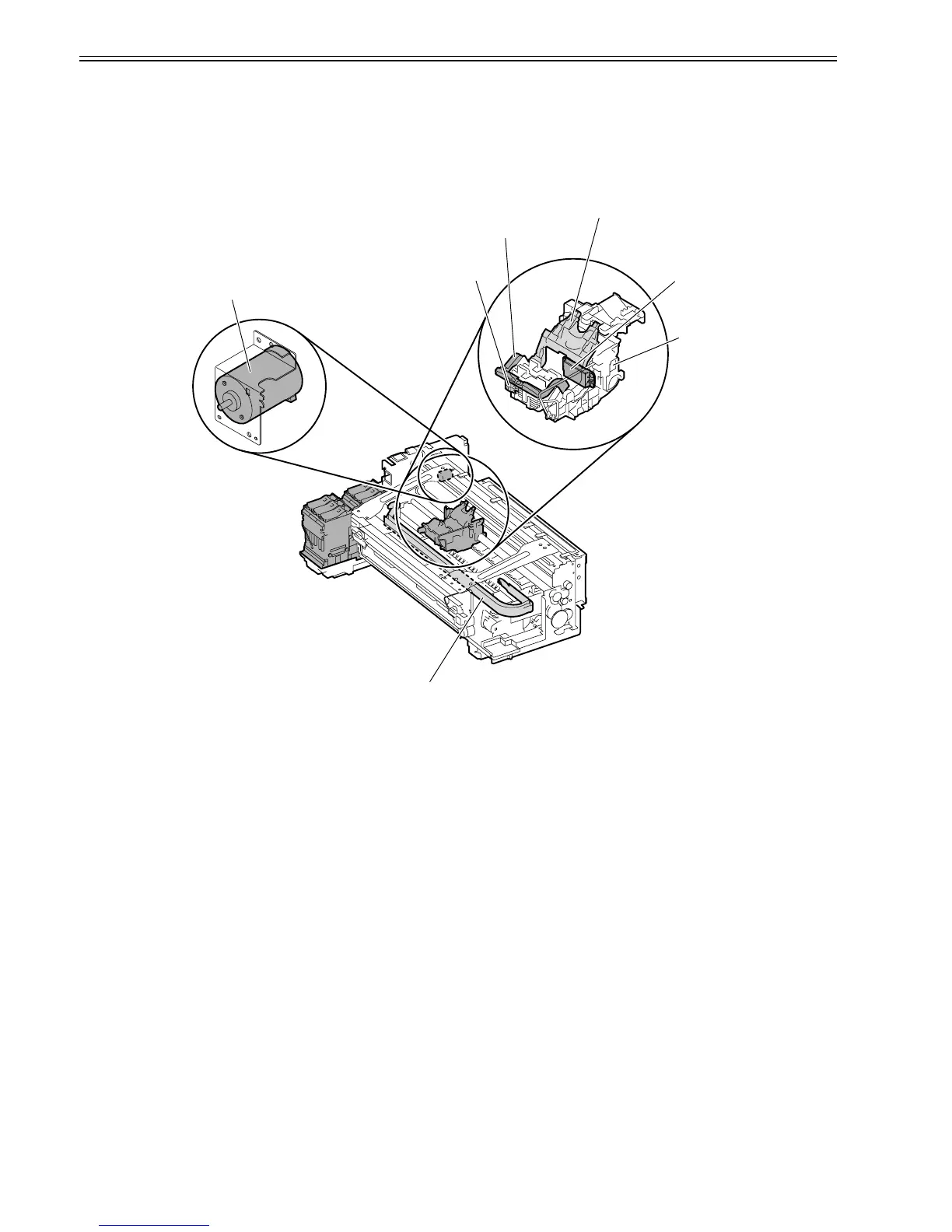
2.3.2.3.2 Structure of Carriage Unit
0013-4891
a) Printhead mounting unit
The printhead is secured to the carriage by the printhead fixer lever.
When the printhead is secured to the carriage, the signal contact of the carriage PCB touches the signal contact point of the printhead, allowing print signals to be
transmitted.
The ink passage from the ink tank is connected to the printhead through the ink tube and joint.
F-2-11
b) Ink port
Ink is supplied to the printhead through the ink tubes.
Ink tube run through the ink tube guide mounted on the carriage and move in conjunction with the carriage.
c) Control unit
The carriage PCB is connected to the main controller PCB with a flexible cable. The flexible cable moves in conjunction with the carriage.
A photo-coupler-type encoder is mounted at the top of the rear of the carriage to detect the slit on the linear scale during carriage movement, thus controlling the
print timing.
d) Carriage drive unit
Mechanical misalignment of the printhead in the vertical and horizontal direction and in bidirectional printing can be corrected by changing the print timing using
the "Adjust Printer" option in the Main menu.
The carriage motor (DC motor) moves the carriage back and forth on the platen via the carriage belt.
The carriage home position is the capping position to which the carriage is slowly moved when the power is turned on.
When the position read on the linear scale is set as the home position for position control, the carriage motor moves based on control signal output from the main
controller.
Printhead fixer lever
Carriage motor
Carriage
Ink tube
Joint for ink supply
Printhead fixer cover
Terminal