Chapter 6
6-3
T-6-3
T-6-4
T-6-5
74 AD2 IN/OUT Address and data signal 02
75 AD1 IN/OUT Address and data signal 01
76 AD0 IN/OUT Address and data signal 00
77 GND - GND
78 HDD_LED - N.C.
79 +5V OUT Power supply (+5V)
80 +5V OUT Power supply (+5V)
81 +5V OUT Power supply (+5V)
82 +3.3V OUT Power supply (+3.3V)
83 +3.3V OUT Power supply (+3.3V)
84 +3.3V OUT Power supply (+3.3V)
85 GND - GND
86 GND - GND
87 GND - GND
88 GND - GND
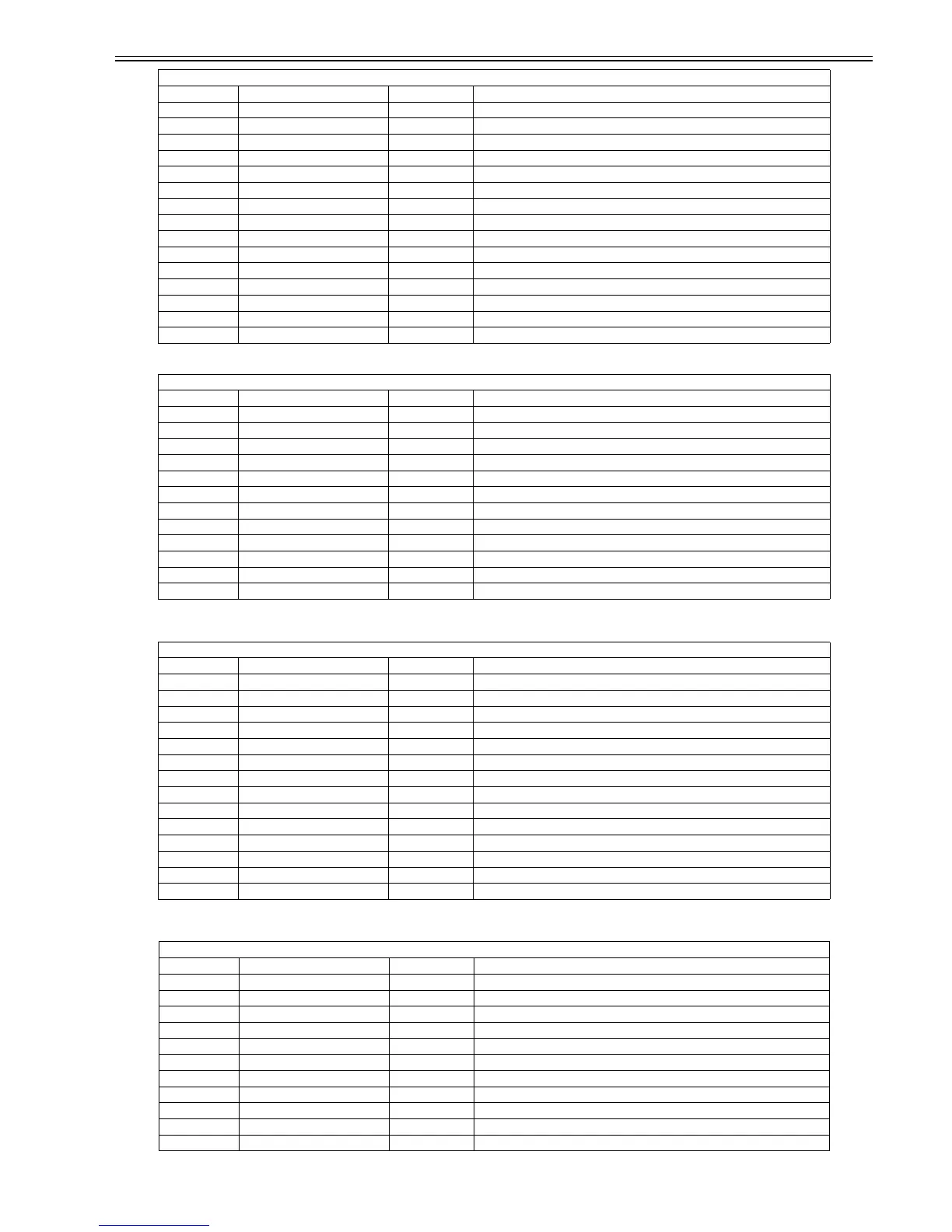
J1201 (network)
Pin Number Signal name IN/OUT Function
1 TX+ OUT Ethernet data TX line (+)
2 TX- OUT Ethernet data TX line (-)
3 RX+ IN Ethernet data RX line (+)
4 - - Not used
5 - - Not used
6 RX- IN Ethernet data RX line (-)
7 - - Not used
8 - - Not used
9 GREEN_LED_C OUT Link LED (green:100Mb/s) cathode terminal
10 GREEN_LED_A OUT Link LED (green:100Mb/s) anode terminal
11 YELLOW_LED_C OUT Link LED (yellow:10Mb/s) cathode terminal
12 YELLOW_LED_A OUT Link LED (yellow:10Mb/s) anode terminal
J1801 (to power supply PCB)
Pin Number Signal name IN/OUT Function
1 HD1_VHFB+ OUT VH feedback voltage +
2 HD1_VHFB- OUT VH feedback voltage -
3 VH IN Power supply (+21.5V)
4 GND - GND
5 VH IN Power supply (+21.5V)
6 GND - GND
7 RGV20(VCC) IN Power supply (+21.5V)
8 GND - GND
9 VM IN Power supply (+26V)
10 GND - GND
11 VM2 IN Power supply (+26V)
12 GND - GND
13 VH_ENB OUT VH power supply ON/OFF signal
14 PW_CONT OUT Normal/power saving switch signal
J2511 (spur motor, spur cam sensor, mist fan, cutter motor, cutter right position sensor)
Pin Number Signal name IN/OUT Function
1 +3V OUT Power supply (+3.3V)
2 GND - GND
3 CUTTER_R_SNS_R IN Cutter right detection sensor signal
4 CUTTER_OUTA OUT Cutter motor driver signal A
5 CUTTER_OUTB OUT Cutter motor driver signal B
6 +3V OUT Power supply (+3.3V)
7 GND - GND
8 HAKUSHA_CAM_SNS_R IN Spur cam sensor output signal
9 HAKUSHA_MOTOR_AM OUT Spur motor drive signal AM
10 HAKUSHA_MOTOR_AP OUT Spur motor drive signal AP
11 FAN_VM OUT Power supply (+26V)
J1001 (IEEE1394 board)
Pin Number Signal name IN/OUT Function