CHAPTER 4 IMAGE FORMATION SYSTEM
COPYRIGHT
©
1999 CANON INC. CANON NP6512/6612/7120/7130/7130F REV.0 AUG. 1999 PRINTED IN JAPAN (IMPRIME AU JAPON)
4-20
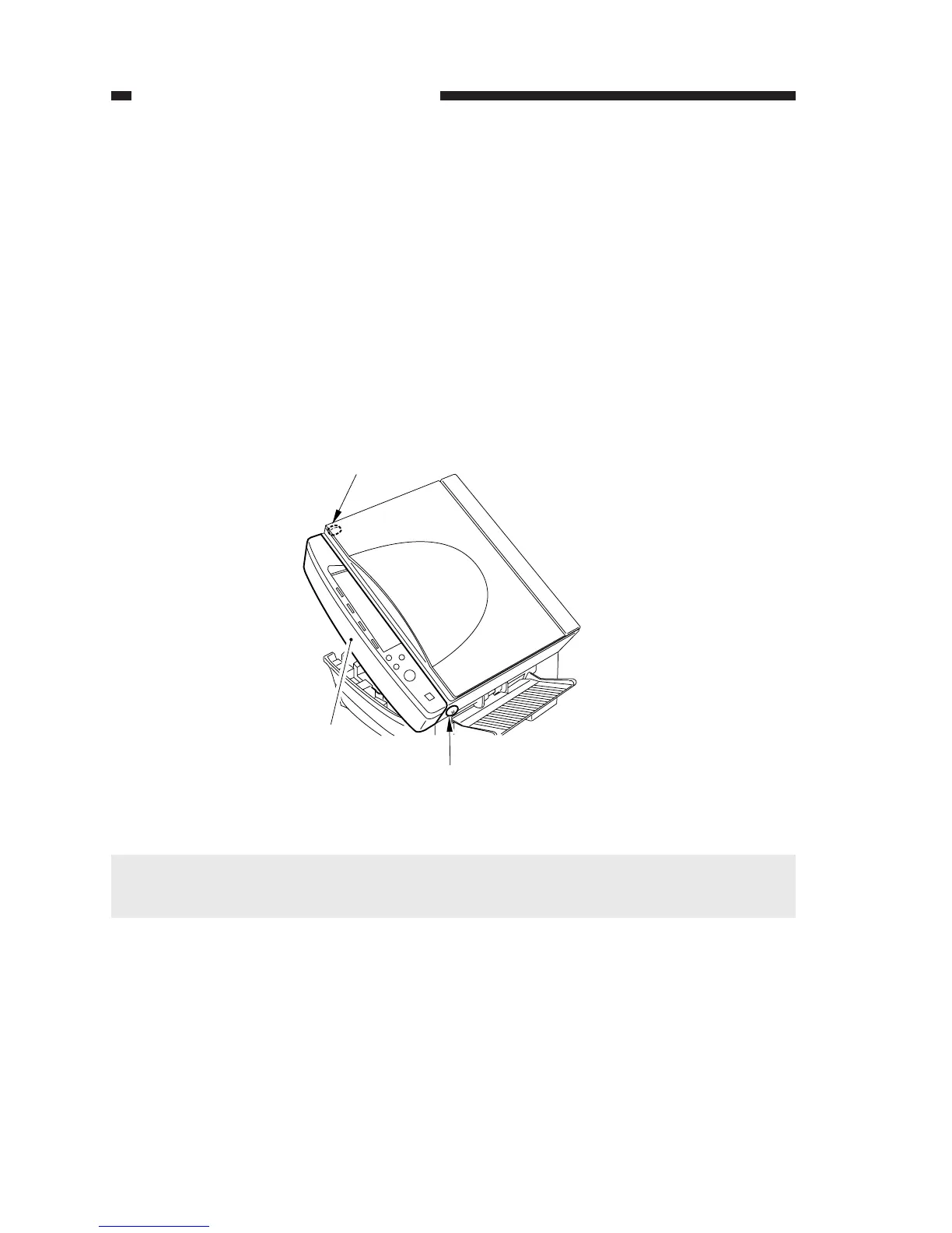
Figure 4-114
3. AE Adjustment (VR102, VR103)
If you have replaced the scanning lamp or the AE sensor PCB, be sure to make the following
adjustments:
Making Adjustments
Before the Work
• Obtain a newspaper more or less even in density. (Avoid ones with photos or large charac-
ters.)
• Obtain five sheets of white sheets of paper
• Check to make sure that the intensity of the scanning lamp has been adjusted properly when
you have replaced the scanning lamp.
• Set the density correction dial (VR107) to the middle setting.
1) Open the top unit; then, remove the two screws [1], and detach the front upper cover [2].
[1]
[1]
[2]
Caution:
The flexible cable for the control panel is connected to the upper front cover; disconnect the
cable from the DC controller PCB.



 To Next Page