CHAPTER 3 EXPOSURE SYSTEM
COPYRIGHT
©
1999 CANON INC. CANON NP6512/6612/7120/7130/7130F REV.0 AUG. 1999 PRINTED IN JAPAN (IMPRIME AU JAPON)
3-1
Item
Lamp
Scanning
Scanner position detection
Ratio variation
Lens drive control
Scanner drive control
Protective function
Description
Halogen
By moving the No. 1 mirror mount
By a sensor (scanner home position sensor; PS1)
Main scanning direction:by varying the optical length
Sub scanning direction:by varying the speed of the No. 1 mirror mount
Scanner/lens drive motor (M2)
Fixed focal point lens unit
Mobile No. 4/5 mirror unit
Scanner/lens drive motor (M2)
Scanner thermistor (TH2)
By a fuse (blows in response to overheating of the scanning lamp to cut
power to the lamp)
• Thermal fuse (FU1; blows at 128°C)
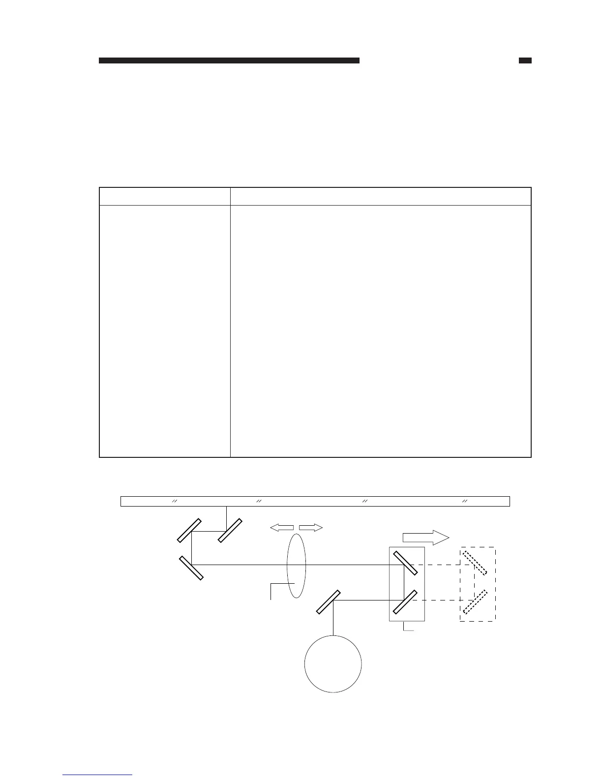
Table 3-101
Figure 3-101
Photosensitive
drum
Fixed focal point lens
Enlarge Reduce
Moves for enlargement/
reduction
No. 4/5 mirror unit
Copyboard glass
I. OPERATIONS
A. Outline
Table 3-101 shows the major functions of the exposure system.