CHAPTER 3 EXPOSURE SYSTEM
COPYRIGHT
©
1999 CANON INC. CANON NP6512/6612/7120/7130/7130F REV.0 AUG. 1999 PRINTED IN JAPAN (IMPRIME AU JAPON)
3-7
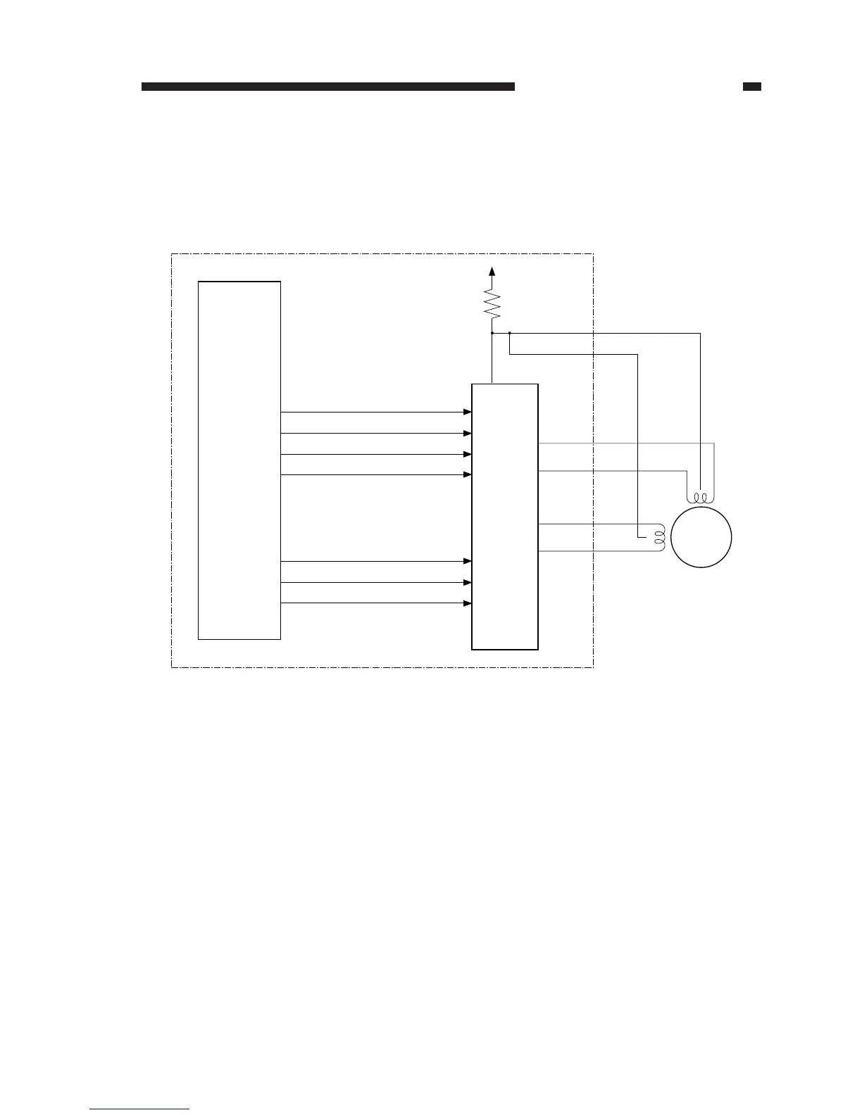
Figure 3-107
Current switching signal 1
Current switching signal 2
Current switching signal 3
(Q101)
(Q109)
DC controller PCB
A
A*
B
B*
SC-COM
SC-COM
J110
SC-A
SC-A*
SC-B
SC-B*
M2
Motor
driver
circuit
+24VU
R399
Microprocessor
5. Controlling the Scanner/Lens Drive Motor
a. Outline
The scanner/lens drive motor (M2) is a 4-phase stepping motor. The timing at which the drive
power (SC-COM) and pulses (SC-A, SCA*, SC-B, SC-B*) are generated is controlled to turn on/
off the scanner/lens drive motor (M2) or to switch the direction of its rotation.



 To Next Page